
Electronically controlled locking differential having under-dash control system

a technology of under-dash control and electric control, which is applied in the direction of instruments, transportation and packaging, gearing, etc., can solve the problems of increasing the cost and time of installation, time-consuming and complicated installation, and negatively affecting the aesthetics of the vehicle interior, so as to prevent actuation of the differential, avoid time-consuming, complicated, or costly. , the effect of safety and better control

Inactive Publication Date: 2012-02-07
EATON CORP
View PDF23 Cites 7 Cited by
  • Summary
  • Abstract
  • Description
  • Claims
  • Application Information

AI Technical Summary

Benefits of technology

The solution enables easy, cost-effective installation without damaging the dashboard, provides enhanced control and feedback, prevents premature wear, and extends battery life by ensuring the differential resets when power is off, offering improved traction and off-road performance.

Problems solved by technology

However, installation of this type of differential into the 4WD vehicle typically requires drilling or boring a hole through the dashboard to mount the relay, route wires, and install the switch that activates and deactivates the differential.
Several disadvantages are associated with this installation.
In particular, this installation is time-consuming and complicated by requiring modification of the dashboard and complicated wiring.
In addition, improper drilling or boring can damage the dashboard, negatively affect the aesthetics of the vehicle interior, and increase cost and time of the installation.

Method used


Image

  • Electronically controlled locking differential having under-dash control system
  • Electronically controlled locking differential having under-dash control system
  • Electronically controlled locking differential having under-dash control system

Examples


Embodiment Construction

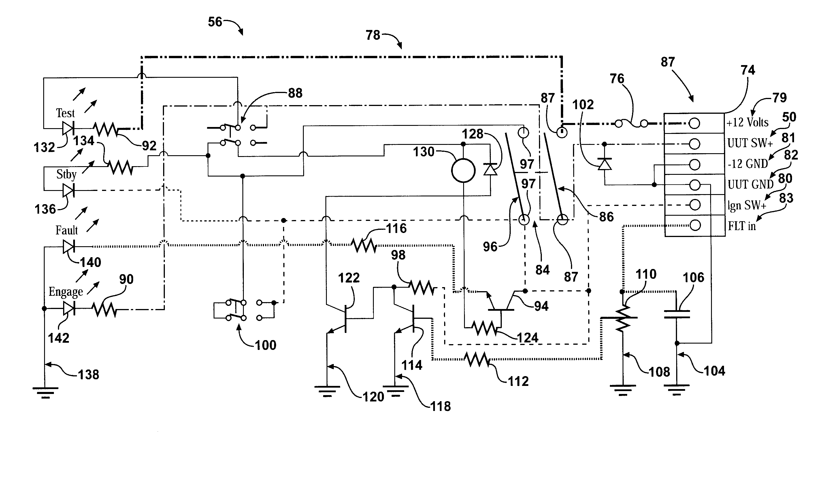
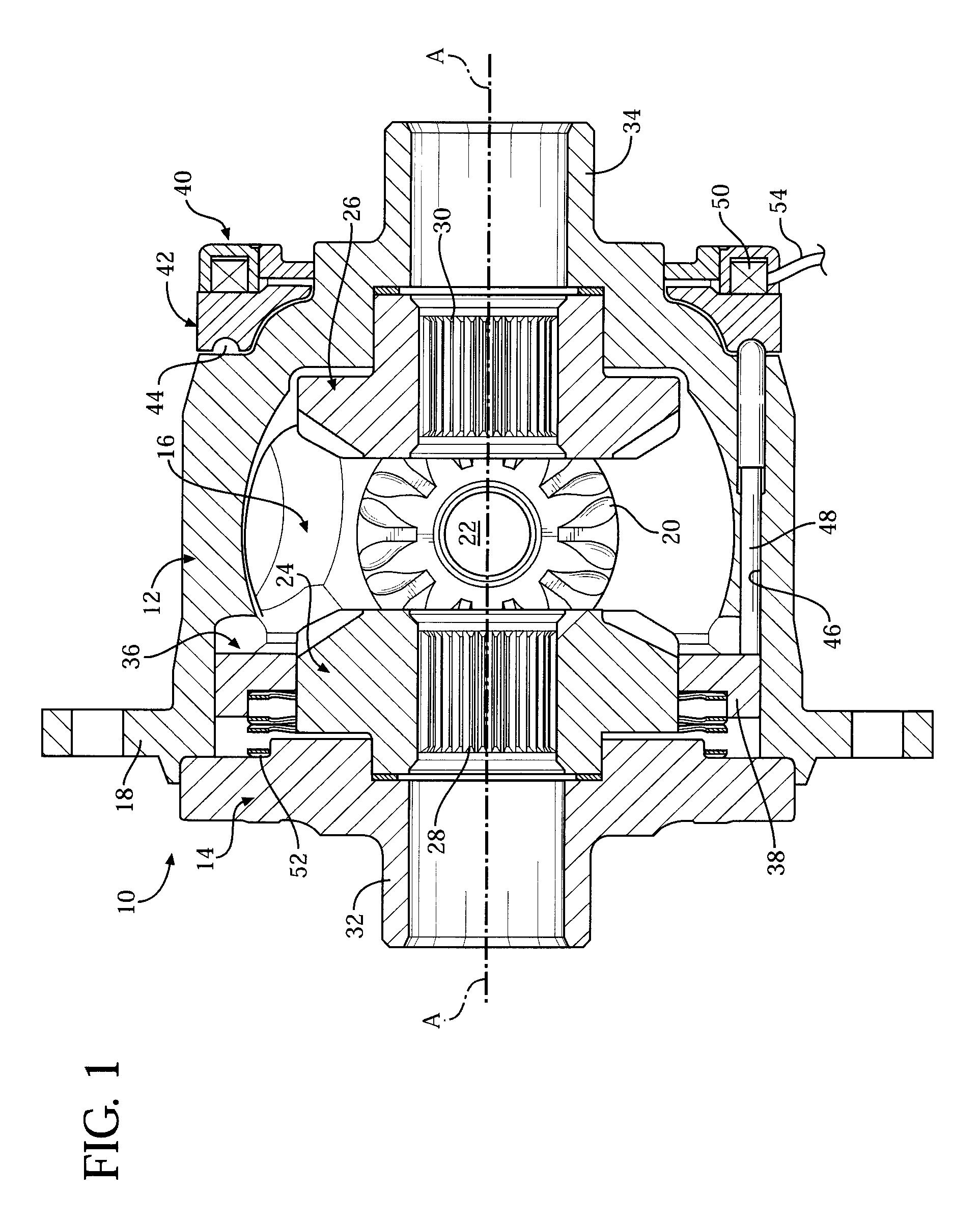
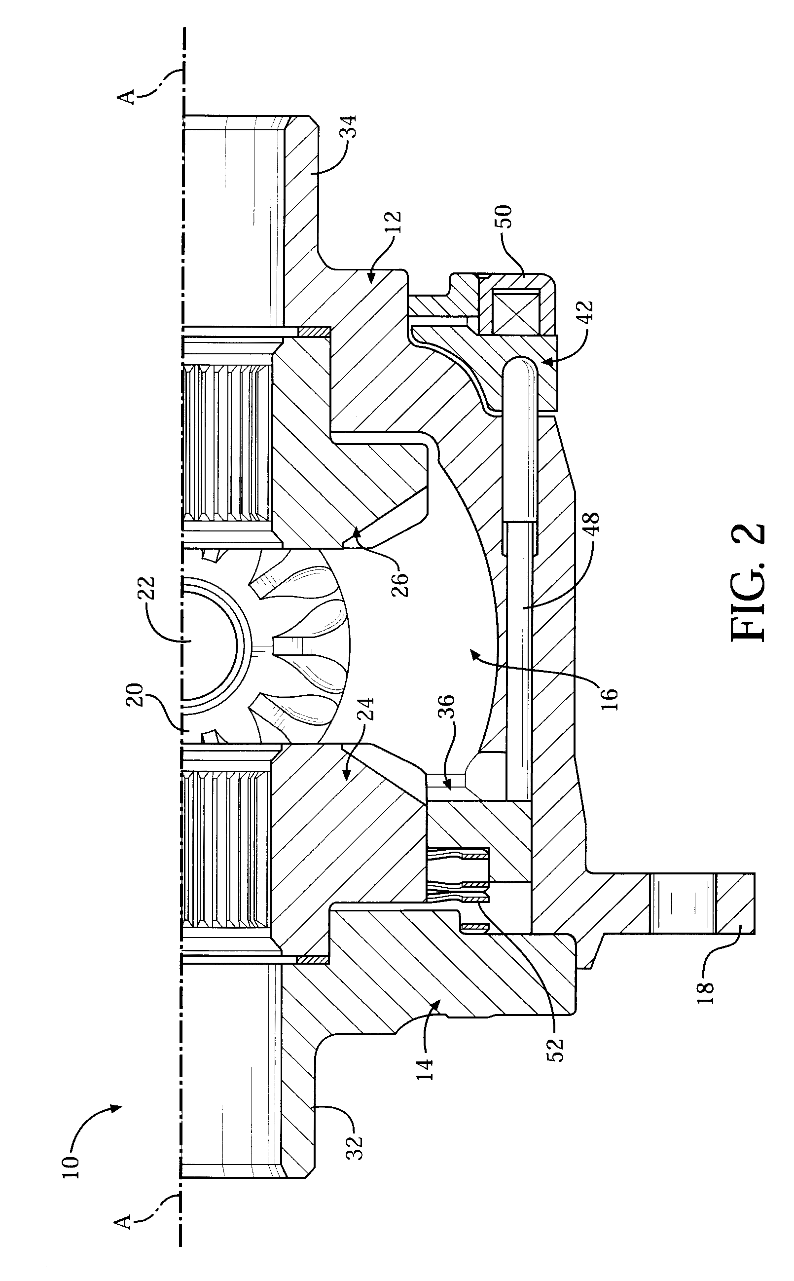
[0014]Referring now to the figures, where like numerals are used to designate like structure, one embodiment of an electronically controlled locking differential having an under-dash control system of the present invention is generally indicated at 10. It should be appreciated by those having ordinary skill in the related art that the differential 10 can be employed in 4WD vehicles, in particular, and any suitable vehicles, in general. It should also be appreciated that the control system of the present invention can be employed with any suitable electronically controlled locking differential. The one described below and shown in FIGS. 1 and 2 is only exemplary, and the control system can be employed with an electronically controlled locking differential that is structurally and functionally different than this one. It should also be appreciated that the control system can be employed by an OEM or in the aftermarket. In the latter case, the control system is adapted to be mounted un...


PUM


Abstract

An electronically controlled locking differential includes an electromagnetic coil and a control system adapted to control operation of the differential. The control system has a module adapted to be mounted under a dashboard of a vehicle and a circuit electrically interfacing with the module. The circuit has a latching switch that is electrically connected to first and / or second sources of power and adapted to provide latching power of the differential. A latching component is electrically connected to the latching switch and adapted to provide latching power of the differential. The circuit is disabled when power to the control system is turned off and in “standby” mode when power to the control system is turned on. Upon the latching switch being activated, current flows through the circuit to activate the latching component, and the differential is actuated.

Description

BACKGROUND OF THE INVENTION[0001]1. Field of the Invention[0002]The present invention relates, in general, to electronically controlled locking differentials and, in particular, to an electronically controlled locking differential having an under-dash system adapted to control operation of the differential.[0003]2. Description of the Related Art[0004]In automotive applications, an electronically controlled locking differential of the related art may be actuated either manually and is designed expressly for a four-wheel-drive (4WD) vehicle to allow the differential to be locked or unlocked when it is so desired. The driver can lock the front and / or rear wheels by manually activating a switch or button mounted to a dashboard or console of the vehicle. This type of torque-controlling device is well-known in the aftermarket. More specifically, an aftermarket system including the differential can be installed using a large push-button switch, which is adapted to be mounted to the dashboa...

Claims


Application Information

Patent Timeline
Patent Type & Authority Patents(United States)
IPC IPC(8): B60K17/00
CPCB60K23/04F16H48/30F16H48/24F16H2048/204F16H2048/346
Inventor DAYTON, TERRY ANDREW
Owner EATON CORP
Learn More