Electric linear-motion actuator and electric brake assembly

a technology of linear motion and actuator, which is applied in the direction of mechanical equipment, gearing, hoisting equipment, etc., can solve the problems of difficult compact design of electric linear motion actuator, difficult to ensure a sufficient stroke of linear motion, and inability to increase the power to the level required in electric brake systems, so as to prevent the separation of the rib-forming member and facilitate the formation

Inactive Publication Date: 2012-02-07
NTN CORP
View PDF14 Cites 12 Cited by
  • Summary
  • Abstract
  • Description
  • Claims
  • Application Information

AI Technical Summary

Benefits of technology

[0011]By forming the helical groove in the radially outer surface of each planetary roller which is equal in pitch to the helical rib and different in lead angle from the helical rib, and in which the helical rib is engaged, the linear movement of the planetary rollers relative to the rotary motion of the rotor shaft is determined by the difference in lead angle between the helical grooves and the helical rib. This makes it possible to increase the reduction rate of the linear motion and thus the linear driving force.
[0020]By providing means for restricting end surfaces of the rib-forming member, which is fixed to the helical groove, it is possible to prevent separation of the rib-forming member, thereby making it possible to form the helical rib, which is configured to engage in the helical grooves formed in the planetary rollers, to design dimensions.

Problems solved by technology

Ball-screw mechanisms and ball-ramp mechanisms used in such conventional electric linear-motion actuators have the ability to increase power to some extent by motion converting means that moves along a thread having a lead or an inclined cam surface, but cannot increase power to a level required e.g. in electric brake systems.
In the case of ball-ramp mechanisms, if the inclination angle of the cam surface is reduced, it is difficult to ensure a sufficient stroke of the linear motion.
But if a separate speed reducing mechanism such as a planetary gear speed reducing mechanism is mounted, it becomes difficult to compactly design the electric linear-motion actuator.
But there is a limit below which the lead angle of the helical rib cannot be reduced.
Thus, there is a limit above which the linear driving cannot be increased.

Method used


Image

  • Electric linear-motion actuator and electric brake assembly
  • Electric linear-motion actuator and electric brake assembly
  • Electric linear-motion actuator and electric brake assembly

Examples


Embodiment Construction

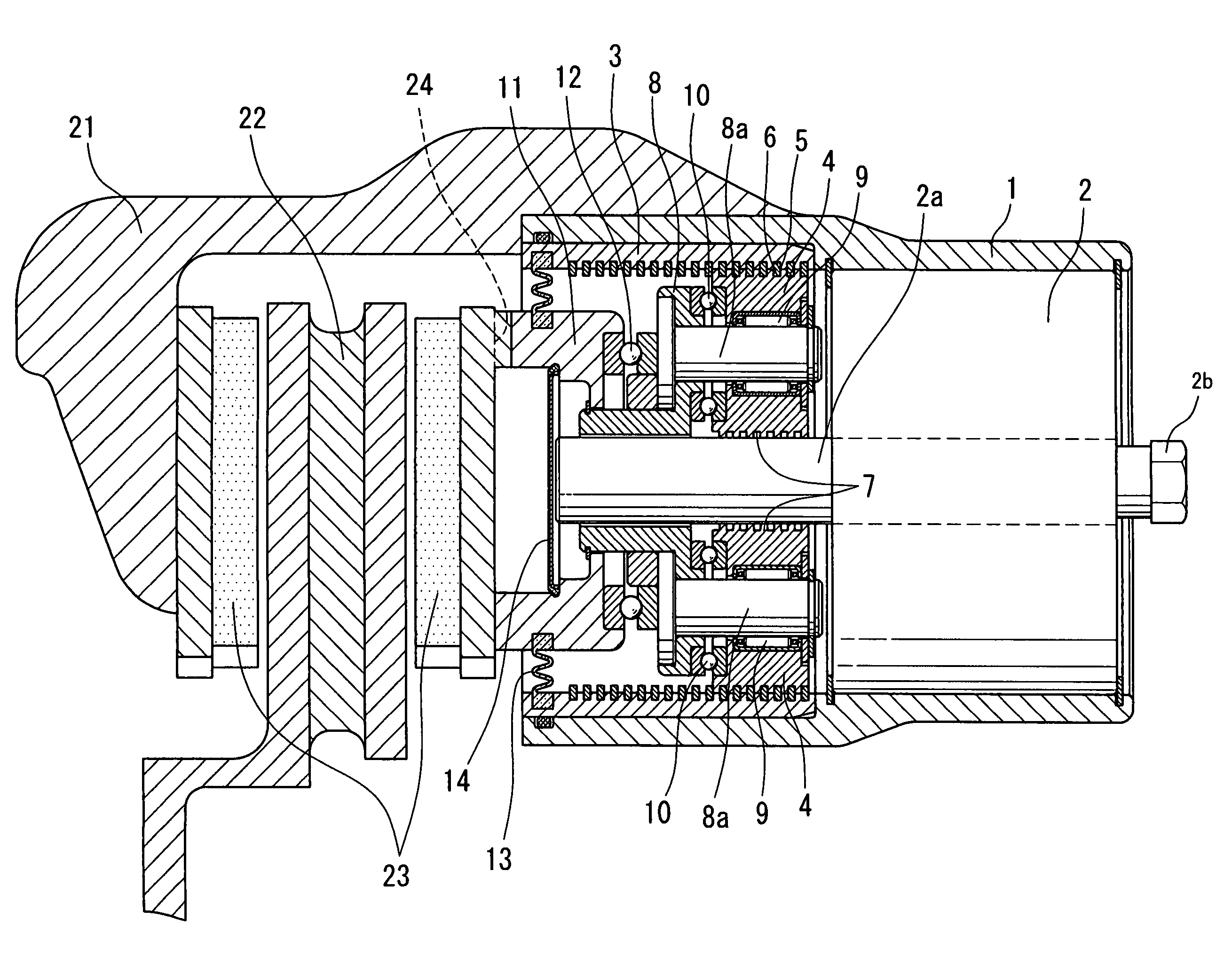
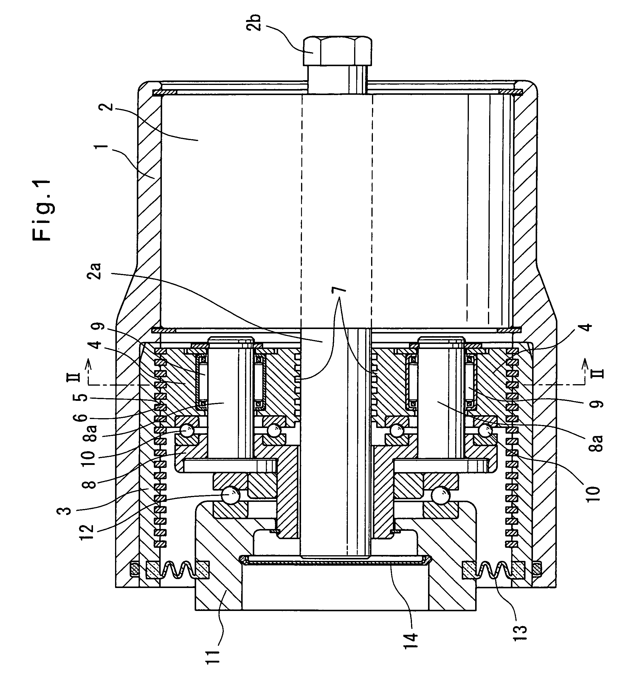
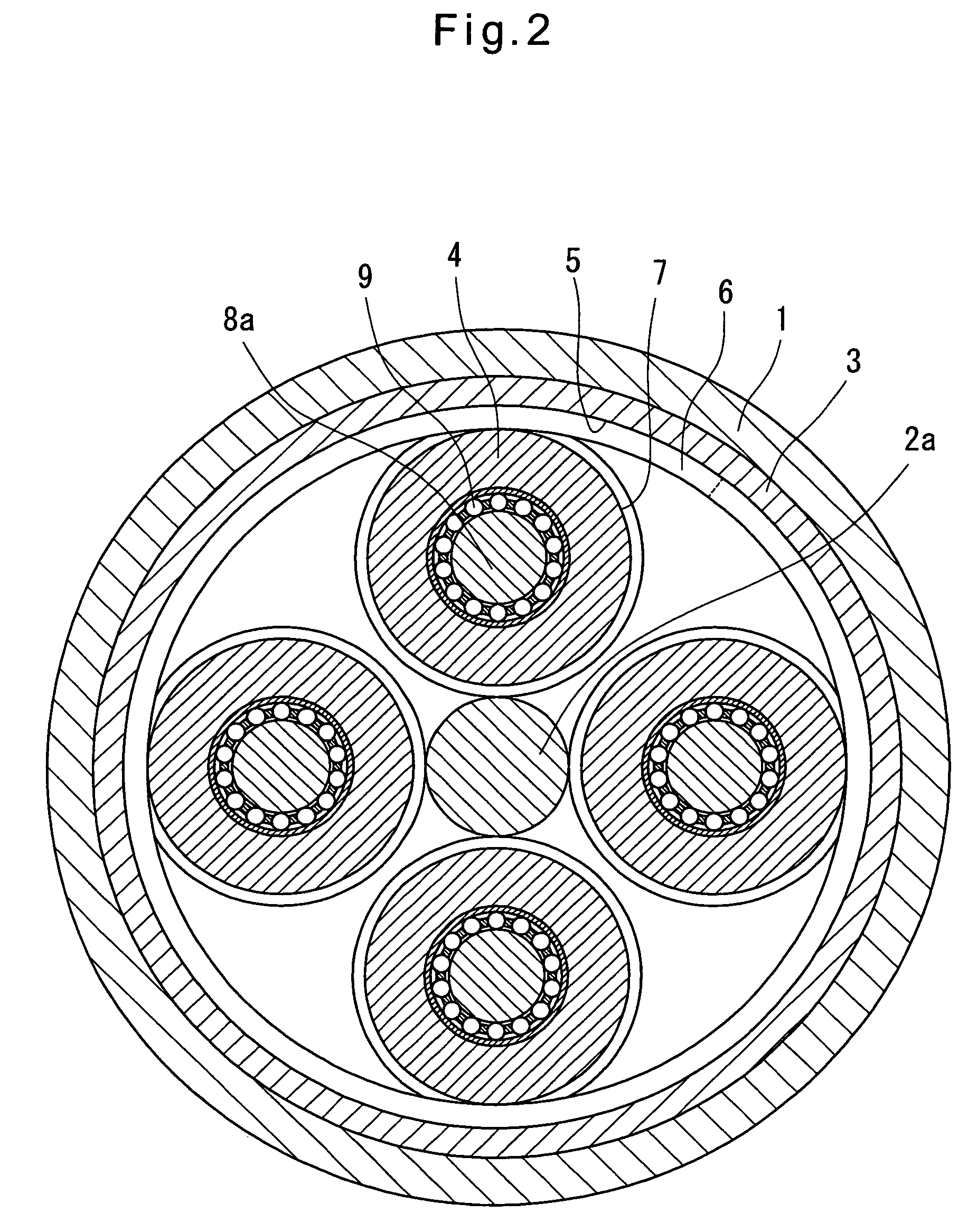
[0030]The embodiments of the invention are now described with reference to the drawings. FIGS. 1 to 4 show the first embodiment. As shown in FIGS. 1 and 2, the electric linear-motion actuator of this embodiment includes an electric motor 2 mounted in a cylindrical casing 1 at one end thereof, and an outer ring member 3 mounted in the casing 1 at the other end. Between the radially inner surface of the outer ring member 3 and the radially outer surface of a rotor shaft 2a of the electric motor 2, four planetary rollers 4 are disposed with a negative gap so that the planetary rollers 4 rotate about the axis of the shaft 2a while simultaneously rotating about their own axes. The rotor shaft 2a protrudes from the end of the casing 1 opposite to its end where the planetary rollers 4 are mounted. At the protruding end thereof, the shaft 2a has a hexagonal head 2b so that the shaft 2a can be rotated with e.g. a wrench. Hardening treatment is applied to the radially outer surfaces of the pl...


PUM


Abstract

An actuator has planetary rollers disposed between a rotor shaft of an electric motor and an outer ring member fixed around the rotor shaft. The planetary rollers are rotated about the axis of the rotor shaft and about their own axes, thereby converting rotary motion of the rotor shaft to linear motion of the planetary rollers A helical groove is formed in the radially outer surface of each planetary roller in which a helical rib formed on the radially inner surface of the outer ring member is received. The helical groove has a pitch equal to that of the helical rib and a lead angle different from that of the helical rib. The amount of the linear motion of the planetary rollers relative to the amount of the rotary motion of the rotor shaft is determined by the difference in lead angle between the helical groove and the helical rib.

Description

TECHNICAL FIELD[0001]The present invention relates to an electric linear-motion actuator for converting the rotary motion of an electric motor to a linear motion, thereby linearly driving a member to be driven, and an electric brake assembly using the electric linear-motion actuator to press a brake member against a member to be braked.BACKGROUND ART[0002]Many electric linear-motion actuators for converting the rotary motion of an electric motor to a linear motion, thereby linearly driving a member to be driven, include a ball-screw mechanism or a ball-ramp mechanism as their motion converter mechanism. Also, in order to obtain large linear driving force with a small-capacity electric motor, many of such actuators include a speed reducing mechanism such as a planetary gear speed reducing mechanism (see e.g. JP patent publication 6-327190A (FIGS. 1 and 5)).[0003]On the other hand, many of the existing vehicle brake assemblies are hydraulic ones. But with the recent introduction of so...

Claims


Application Information

Patent Timeline
Patent Type & Authority Patents(United States)
IPC IPC(8): F16H25/22
CPCF16D65/18F16H25/2252H02K7/06F16H13/06F16D2121/24F16D2125/405Y10T74/18272Y10T74/19795
Inventor YAMASAKI, TATSUYA
Owner NTN CORP
Why Eureka
Try Eureka