
Wiring substrate, method of manufacturing wiring substrate, and liquid droplet ejection head

a technology of wiring substrate and manufacturing method, which is applied in the direction of inking apparatus, coupling contact members, coupling device connections, etc., can solve the problems of increased cost or thickness, difficulty in achieving finer wiring or higher density, and increase the cost or thickness. , to achieve the effect of high-density wiring arrangement, preventing short-circuiting, and high-density wiring

Inactive Publication Date: 2012-02-07
FUJIFILM CORP
View PDF11 Cites 6 Cited by
  • Summary
  • Abstract
  • Description
  • Claims
  • Application Information

AI Technical Summary

Benefits of technology

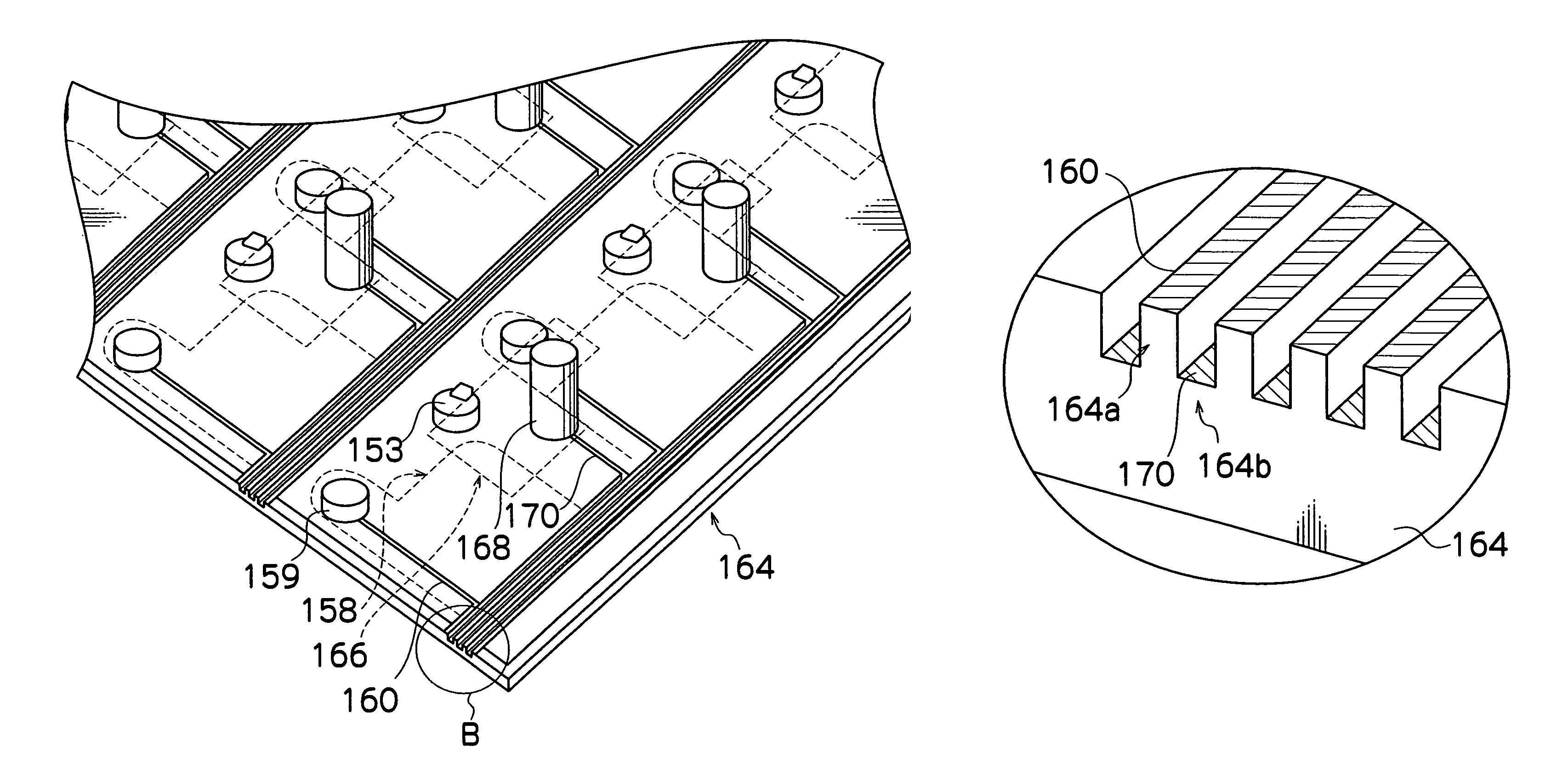
This approach allows for high-density wiring without increasing substrate thickness, preventing short-circuiting, reducing noise, and ensuring excellent flatness and reliability of the wiring substrate, which can be applied to liquid droplet ejection heads.

Problems solved by technology

However, in the related arts described above, wires are only formed on either one of the recess sections or the projecting sections of the substrate, and wires are not formed simultaneously on both the recess sections and the projecting sections.
For example, if wires are formed only in the recess sections of the substrate, then it is difficult to achieve finer wiring or higher density.
Furthermore, in a case of such lamination structure, the process is highly complicated, leading to increased costs or increased thickness.

Method used


Image

  • Wiring substrate, method of manufacturing wiring substrate, and liquid droplet ejection head
  • Wiring substrate, method of manufacturing wiring substrate, and liquid droplet ejection head
  • Wiring substrate, method of manufacturing wiring substrate, and liquid droplet ejection head

Examples


Embodiment Construction

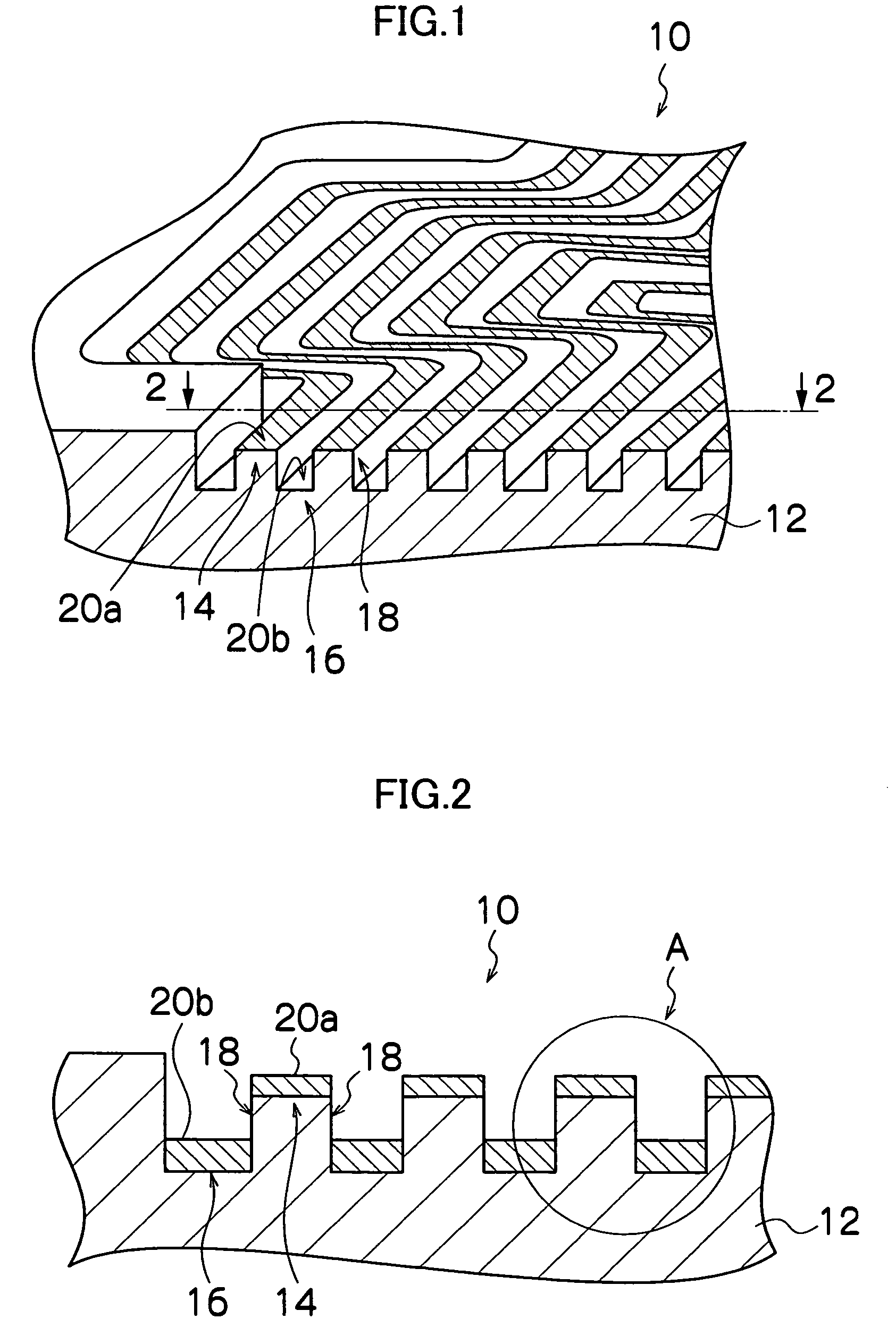
[0039]FIG. 1 shows an oblique view of the general composition of a wiring substrate relating to one embodiment of the present invention.

[0040]In the present embodiment, a wiring pattern for achieving high-density wiring is formed by means of a single thin-film substrate.

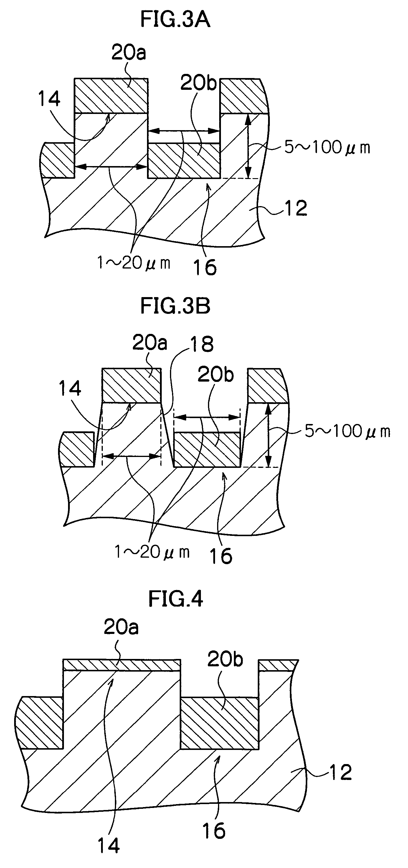
[0041]As shown in FIG. 1, in the wiring substrate 10 according to the present embodiment, a substrate 12 is provided with an undulating shape including projecting sections 14 and recess sections 16, and wires 20a and 20b formed respectively in the projecting sections 14 (and more specifically, the surfaces of the peak sections of the projecting shapes) and the recess sections 16 (and more specifically, the surfaces of the bottoms of the groove shapes). The side faces 18 of the grooves between the projecting sections 14 and the recess sections 16 are insulated.

[0042]Furthermore, it is suitable to use a non-conductive material for the material of the substrate 12. There are no particular restrictions on the non-conduct...


PUM


Abstract

The wiring substrate having a recess section and a projecting section formed on at least one surface of the wiring substrate, and wires formed on both the recess section and the projecting section.

Description

BACKGROUND OF THE INVENTION[0001]1. Field of the Invention[0002]The present invention relates to a wiring substrate, a method of manufacturing a wiring substrate and a liquid droplet ejection head, and more particularly, to a wiring substrate, a method of manufacturing a wiring substrate and a liquid droplet ejection head for achieving high-density wiring by forming wires respectively in a recess section and a projecting section.[0003]2. Description of the Related Art[0004]In the related art, it has been sought to reduce the size and weight of various electrical devices. For example, there have been demands for reducing the size and increasing the density of inkjet heads used in inkjet recording apparatuses, and the like.[0005]In order to reduce the size of equipment, it is necessary to arrange the electrical wires which supply signals for driving the semiconductor elements, or the like, at a high density. Various technologies for manufacturing high-density wiring substrates have be...

Claims


Application Information

Patent Timeline
Patent Type & Authority Patents(United States)
IPC IPC(8): B41J2/05B41J2/14B41J2/045
CPCB41J2/14233H05K1/0265H05K3/041H05K3/06H05K3/107B41J2002/14459B41J2002/14491B41J2202/18H05K3/061H05K3/244H05K2201/09018H05K2201/09036H05K2201/09045H05K2201/09236H05K2201/09736H05K2201/098H05K2201/09827H05K2201/09836H05K2201/09981H05K2203/0108H05K2203/1527
Inventor KOJIMA, TOSHIYAFURUKAWA, GENTARO
Owner FUJIFILM CORP
Learn More