

Ultrasonic transducer, ultrasonic transducer array, and ultrasonic device
a transducer array and ultrasonic technology, applied in the direction of sound producing devices, generators/motors, instruments, etc., can solve the problems of difficult optimization of unstable properties, and difficult control of deflecting diaphragm stress, so as to improve transmission and reception properties, the effect of easy optimization of ultrasonic transducer properties and uniform and stable ultrasonic transducer array properties
- Summary
- Abstract
- Description
- Claims
- Application Information
AI Technical Summary
Benefits of technology
Problems solved by technology
Method used
Image

Examples
first embodiment
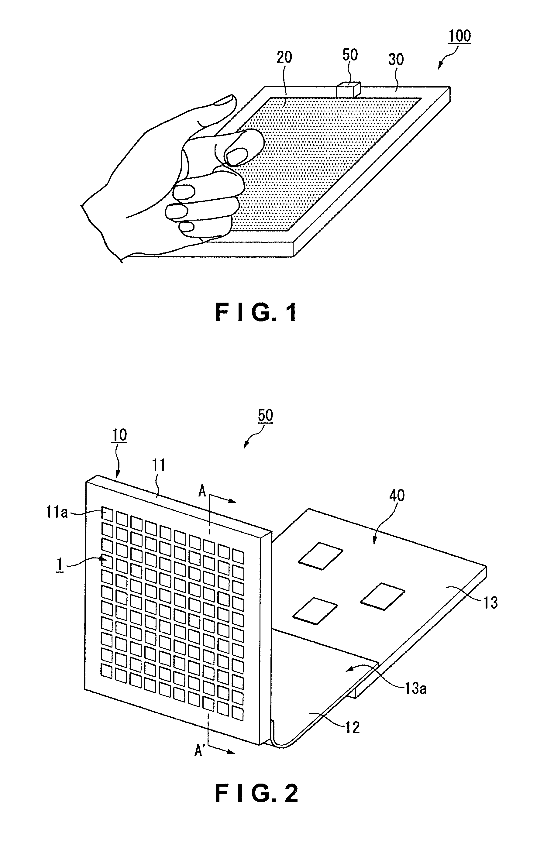
[0043]A first embodiment of the present invention is illustrated below with reference to drawings. In the following figures, the scale of the layers and members has been modified as needed to ensure that each layer and member is large enough to be seen in the figures.
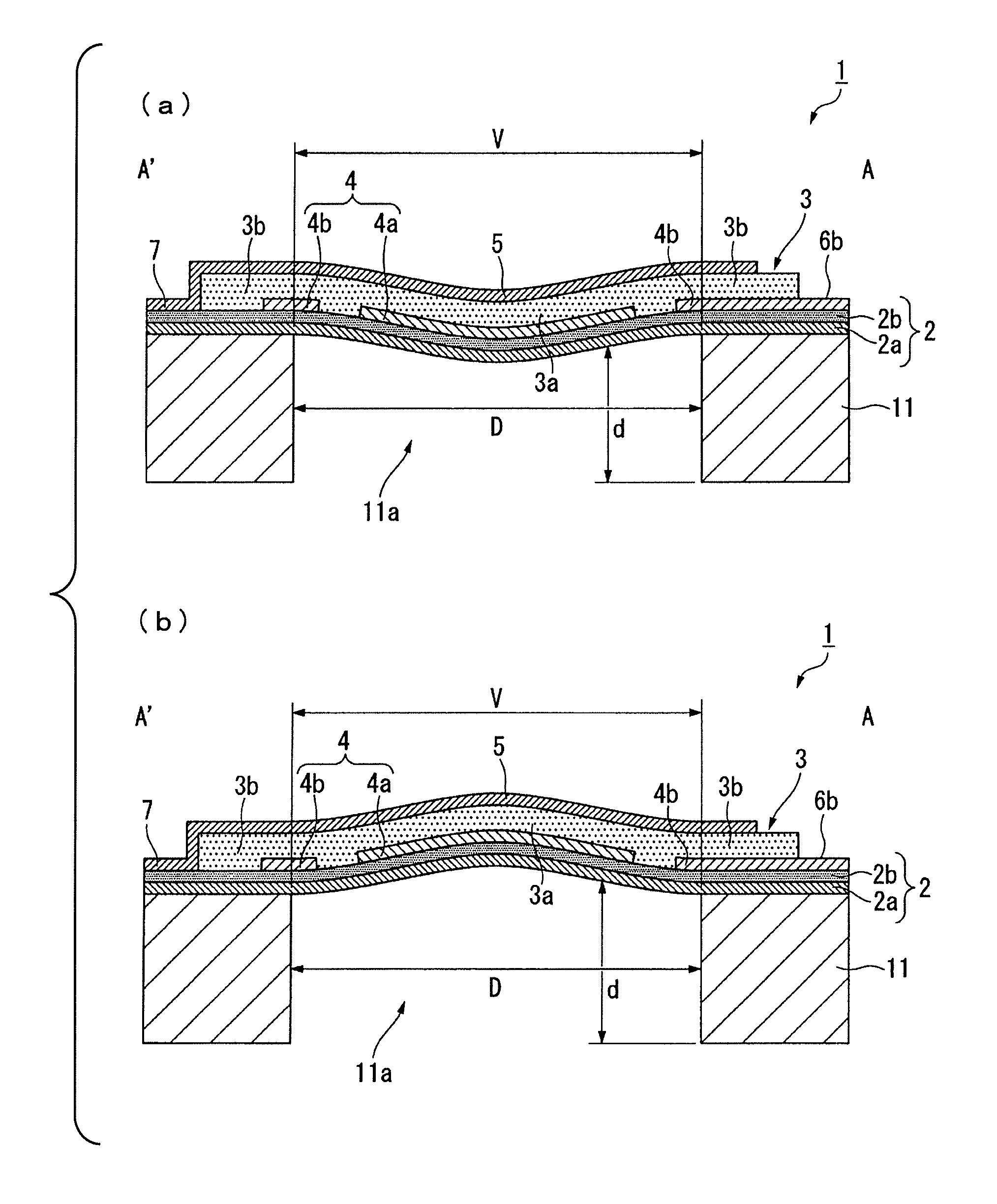
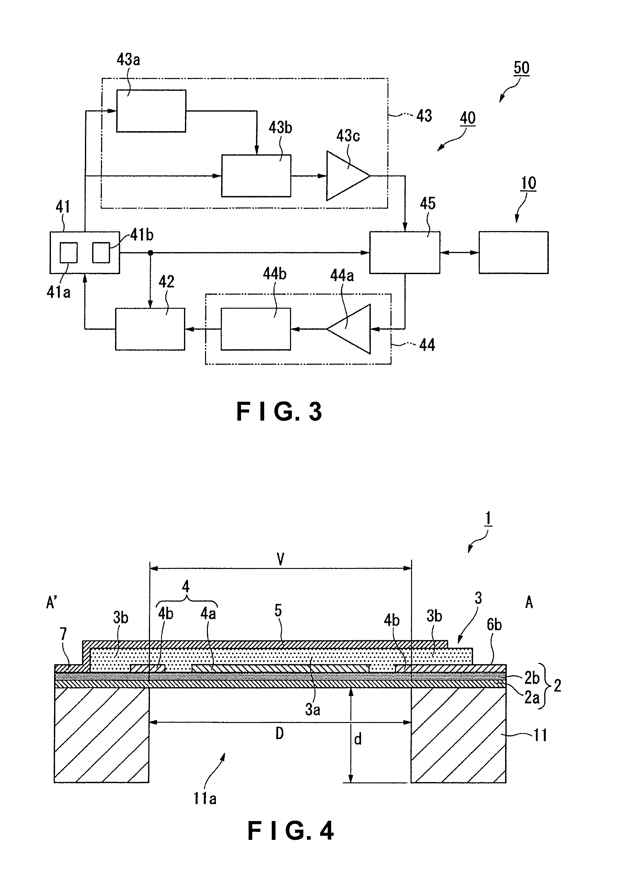
[0044]FIG. 1 is a perspective view schematically representing the structure of a PDA (Personal Data Assistant) 100 in the present embodiment. FIG. 2 is an exploded perspective view schematically representing the structure of an ultrasonic device 50 provided to the PDA 100 in the present embodiment. FIG. 3 is a system configuration diagram schematically representing the structure of the controller 40 (control unit) of the ultrasonic device 50 in the present embodiment. FIG. 3 does not show the structure for applying constant voltage to the second bottom electrode described below.
[0045]As shown in FIG. 1, the main body 30 of the PDA 100 in the present embodiment has a display 20. The display 20 is composed, for example, o...
second embodiment
[0091]A second embodiment of the present invention is described below with reference to FIGS. 1 through 3, 7, and 8. The ultrasonic transducer 1A in the present embodiment is different from the ultrasonic transducer 1 described in the first embodiment above in that the transducer has a plurality of second bottom electrodes 4b1 through 4b4, and also has a plurality of second piezoelectric components 3b1 through 3b4 corresponding to the second bottom electrodes 4b1 through 4b4. The embodiment is the same as the first embodiment in other respects, and the same parts will therefore be identified by the same symbols without further elaboration.
[0092]FIG. 7 is a plan view of the bottom electrode 4A of the ultrasonic transducer 1A in the present embodiment, corresponding to FIG. 5 in the first embodiment. FIG. 8 is an enlarged cross sectional view of the ultrasonic transducer 1A in the present embodiment, corresponding to FIG. 4 in the first embodiment. Here, FIG. 8 is a cross sectional vi...
PUM
 Abstract
Description
Claims
Application Information