
Biasing methods and devices for power amplifiers

a power amplifier and biasing technology, applied in the field of amplifier biasing, can solve the problems of high voltage usually not available in present technologies, interference at charge pump frequency, and more complex circuits

Active Publication Date: 2012-02-07
PSEMI CORP
View PDF2 Cites 73 Cited by
  • Summary
  • Abstract
  • Description
  • Claims
  • Application Information

AI Technical Summary

Problems solved by technology

Such high voltages are usually not available in present technologies and they are provided separately.
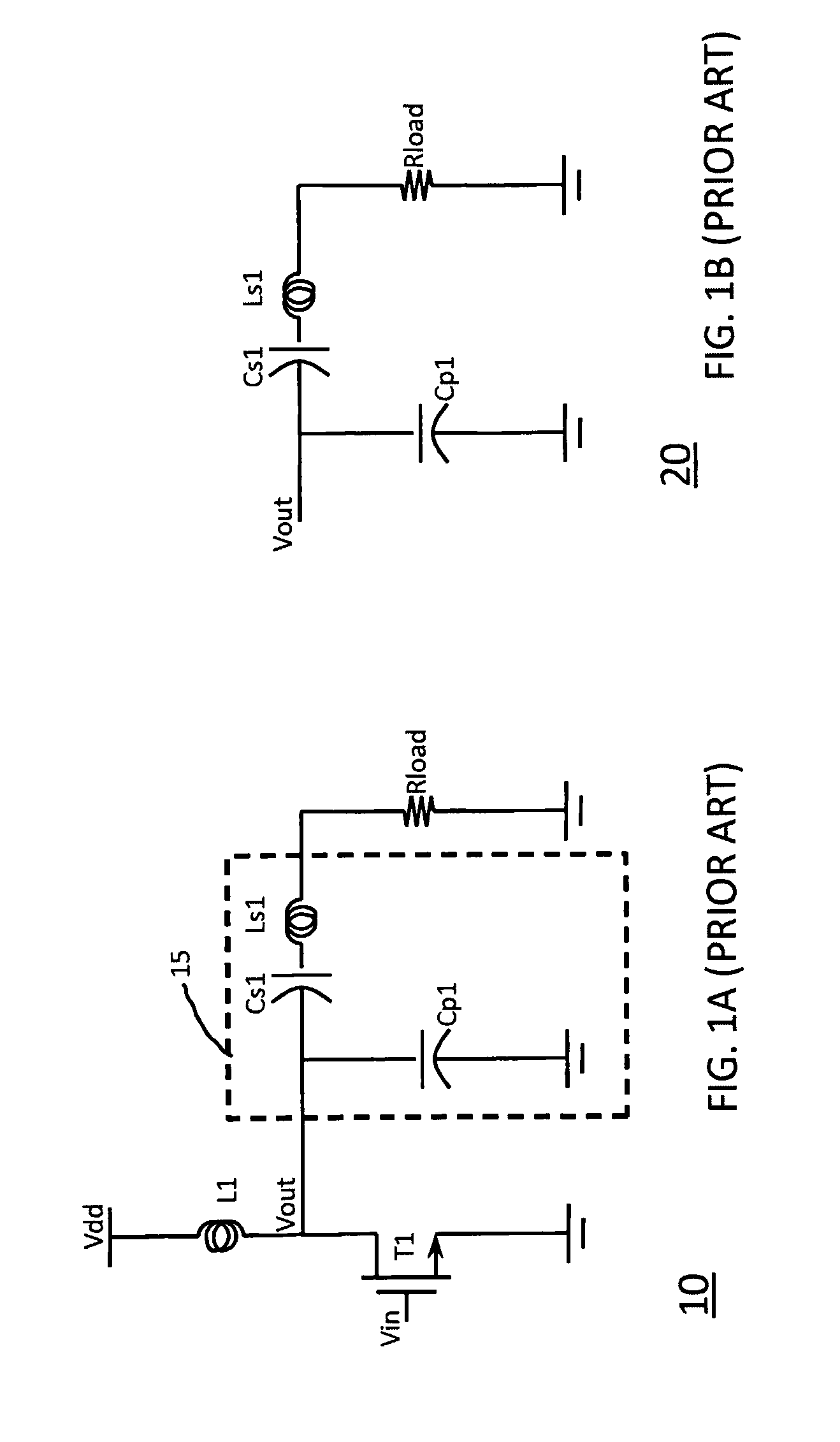
However, using charge pumps to generate bias voltages may result in interference at charge pump frequency.
Also, this solution involves design of more complex circuits.
Moreover, using charge pumps increases the overall power consumption resulting in a lower power amplifier efficiency.

Method used


Image

  • Biasing methods and devices for power amplifiers
  • Biasing methods and devices for power amplifiers
  • Biasing methods and devices for power amplifiers

Examples


Embodiment Construction

[0021]Throughout this description, embodiments and variations are described for the purpose of illustrating uses and implementations of the inventive concept. The illustrative description should be understood as presenting examples of the inventive concept, rather than as limiting the scope of the concept as disclosed herein.

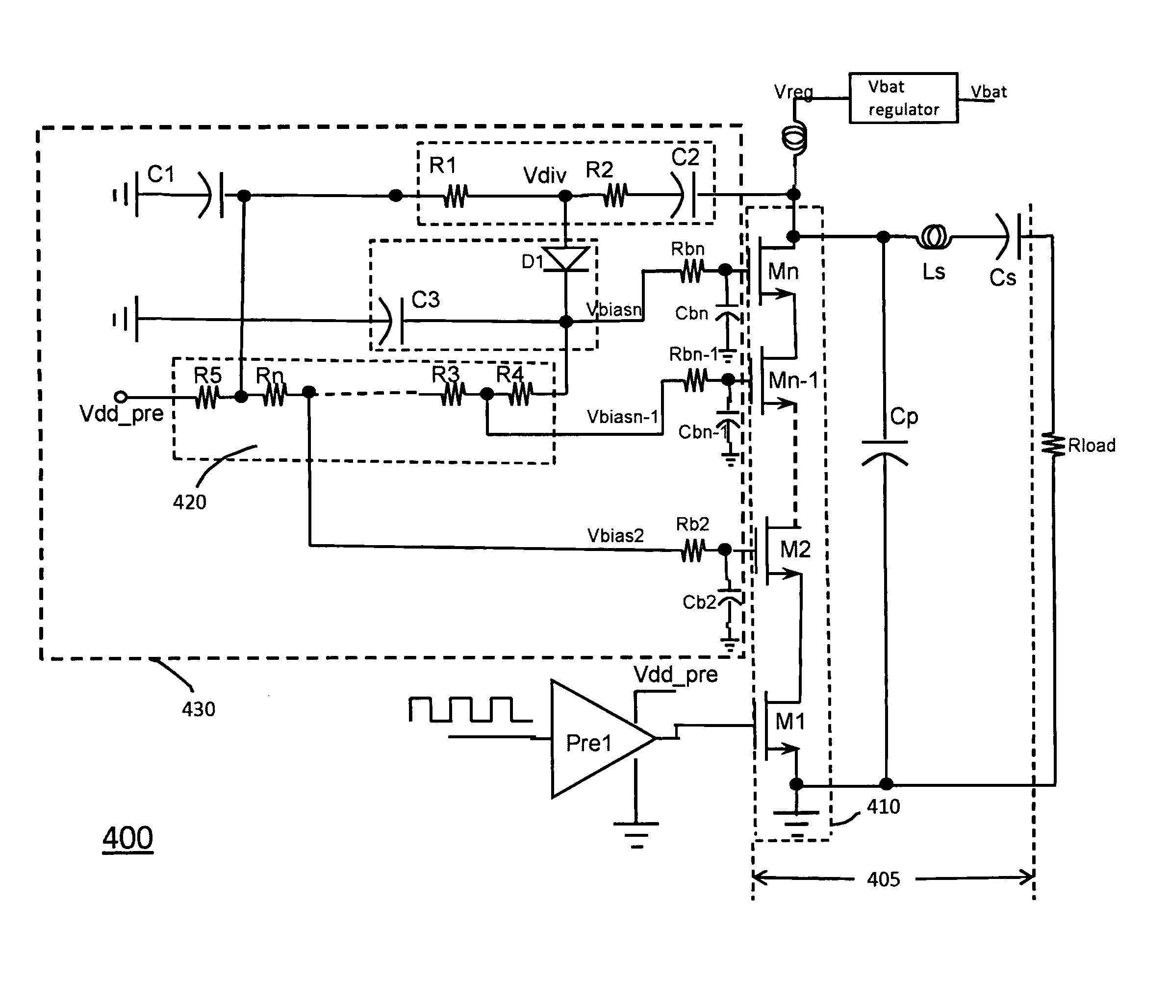
[0022]In particular, biasing methods and devices for use in implementing power amplifiers in accordance with the embodiments of the present disclosure are described. More particularly, biasing methods for use in realizing class-E power amplifiers are described. Class-E amplifiers operate in “switching mode” and as such, they can achieve a much higher efficiency than do typical class-B or class-C amplifiers. See, for example, “Class E-A New Class of High-Efficiency Tuned Single-Ended Switching Power Amplifiers”, Nathan O. Sokal et al. IEEE journal of Solid-State Circuits, Vol, SC-10, NO. 3, June 1975, incorporated herein by reference in its entirety. In other wor...


PUM


Abstract

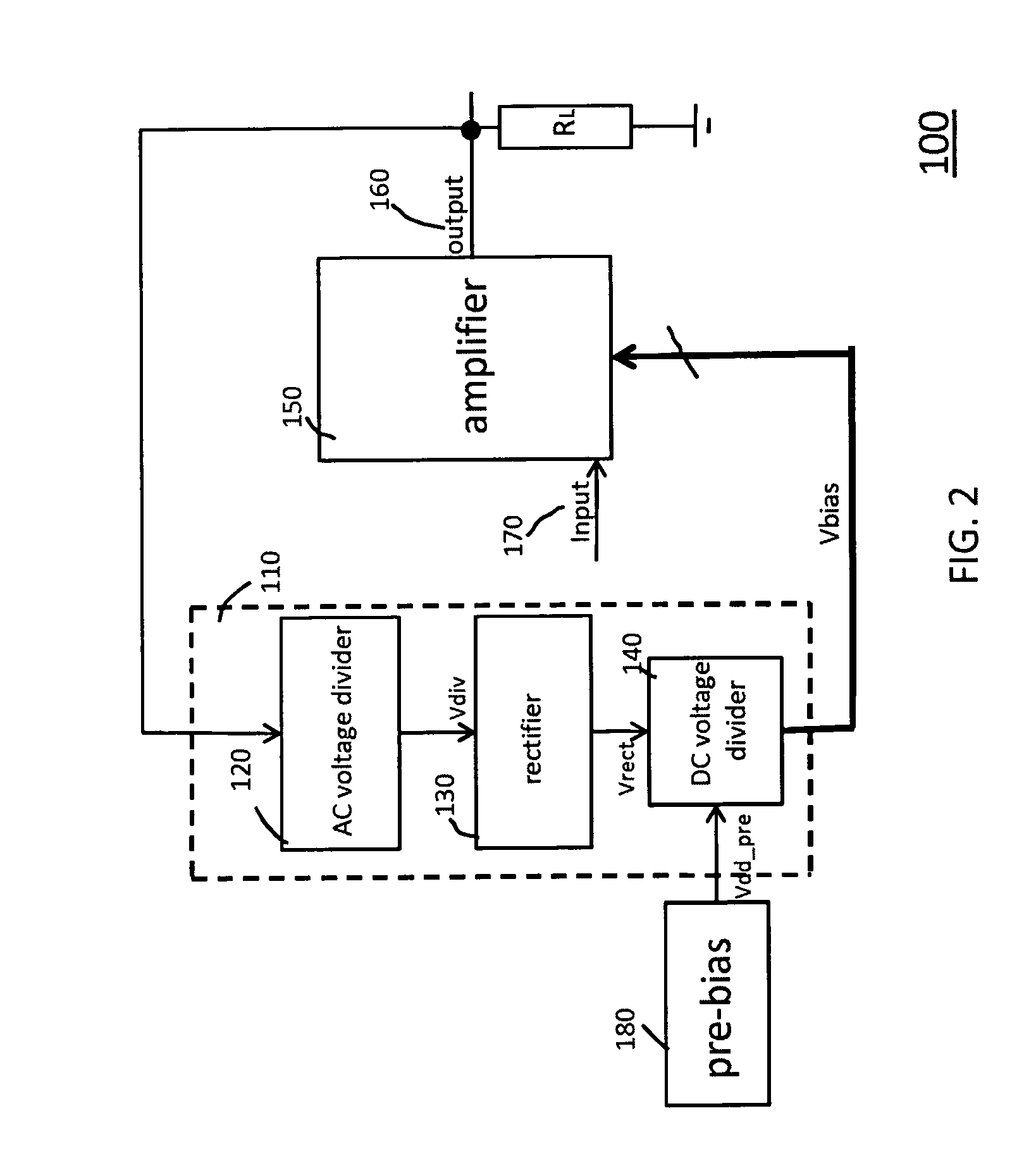
Biasing methods and devices for power amplifiers are described. The described methods and devices use the power amplifier output voltage to generate bias voltages. The bias voltages are obtained using rectifiers and voltage dividers. The described biasing methods and devices can be used with class-E power amplifiers.

Description

BACKGROUND[0001]1. Field[0002]The present teachings relate to amplifier biasing. In particular, the present teachings relate to biasing methods and devices for use in implementing power amplifiers.[0003]2. Description of Related Art[0004]Highly efficient microwave and RF amplifiers producing large output voltages (e.g., 14 to 16 V) are adopted for many applications. In order to be able to handle such large voltages during operation, a CMOS type power amplifier often presents devices arranged in a cascode configuration where the devices are stacked in series. The gates of the power amplifier devices used in the stack have bias voltages that are higher than the battery supply voltage. Such high voltages are usually not available in present technologies and they are provided separately.[0005]A solution to this problem is to use charge pumps. However, using charge pumps to generate bias voltages may result in interference at charge pump frequency. Also, this solution involves design of ...

Claims


Application Information

Patent Timeline
Patent Type & Authority Patents(United States)
IPC IPC(8): H03G3/30
CPCH03F1/301H03F3/2176H03F1/223H03F1/0261H03F2200/18
Inventor AHADIAN, JOSEPH F.SHARMA, VIKASCALANCA, NEILADAMSKI, JAROSLAW E.
Owner PSEMI CORP
Learn More