Method for manufacturing electrosurgical seal plates

a sealing plate and electrosurgical technology, applied in the direction of contact member manufacturing, surgical forceps, controlling lamination, etc., can solve the problems of inability to meet the the manufacturing process may not be suitable for unique and/or complex jaw member and/or seal plate, and the manufacturing process may not be cost effective in certain instances

Active Publication Date: 2012-02-14
TYCO HEALTHCARE GRP LP
View PDF66 Cites 128 Cited by
  • Summary
  • Abstract
  • Description
  • Claims
  • Application Information

AI Technical Summary

Benefits of technology

[0008]The present disclosure provides a method of manufacture for an end effector assembly configured for use with an electrosurgical instrument configured for performing an electrosurgical procedure. The method includes providing a pair of jaw members. A step of the method includes forming one or more seal plates positionable on one of the pair of jaw members. Etching a dam along a side of the one or more seal plates is a step of the method, wherein the etched dam inhibits the flow of a plastic on the one or more seal plate such that a height of the plastic with respect to the at least one seal plate during an overmolding process may be controlled. The method includes positioning the one or more seal plates on the one of the pair of jaw members; and overmolding the seal plate to one or more of the pair of jaw members.

Problems solved by technology

In either instance, forming the seal plates during the manufacture process requires extremely high precession, which may lead to high tolerance stack-ups (e.g., knife blade to knife slot width ratios).
In this instance, however, the bond and / or stop member that secures the stop member to the seal surface of the seal plate is susceptible to shear stresses associated with opening and closing the jaw members of an end effector assembly.
In some instances, however, these manufacturing process may not be suitable for unique and / or complex jaw member and / or seal plate geometries, such as, for example, when one or both of the seal plates requires a knife slot or stop member formed thereon.
Additionally, manufacture of the seal plates via the aforementioned process, in certain instances, may not be cost effective.

Method used


Image

  • Method for manufacturing electrosurgical seal plates
  • Method for manufacturing electrosurgical seal plates
  • Method for manufacturing electrosurgical seal plates

Examples


Embodiment Construction

[0031]Embodiments of the presently disclosed method and system are described in detail with reference to the drawing figures wherein like reference numerals identify similar or identical elements. As used herein, the term “distal” refers to that portion which is further from the user while the term “proximal” refers to that portion which is closer to the user.

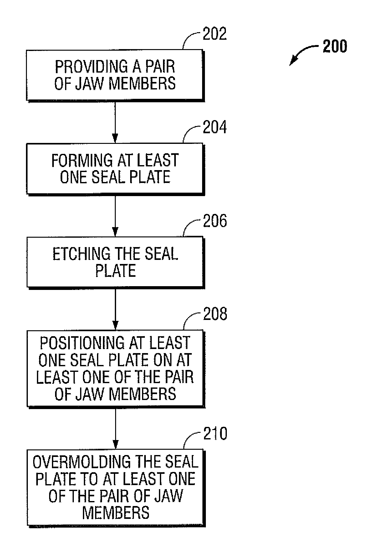
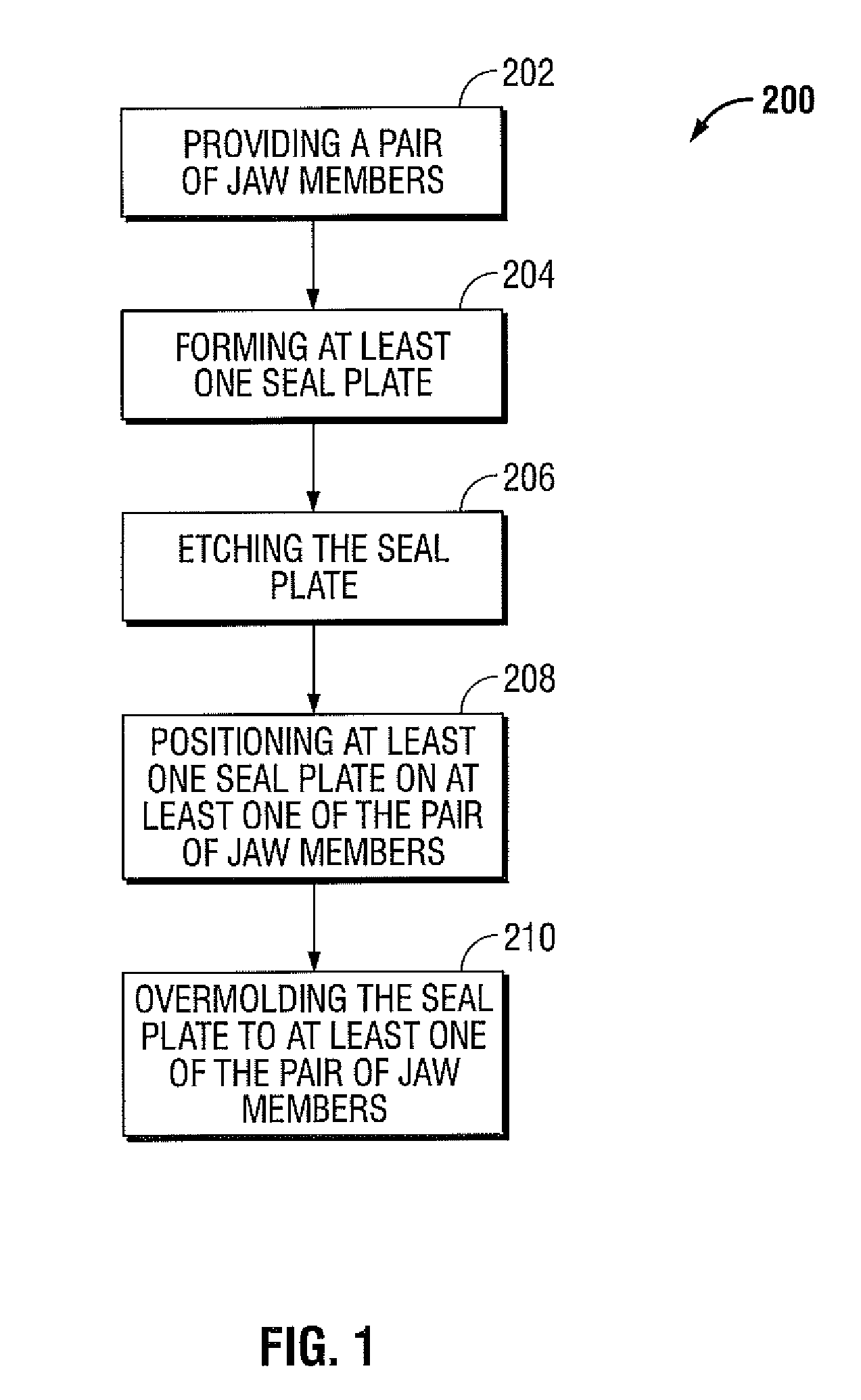
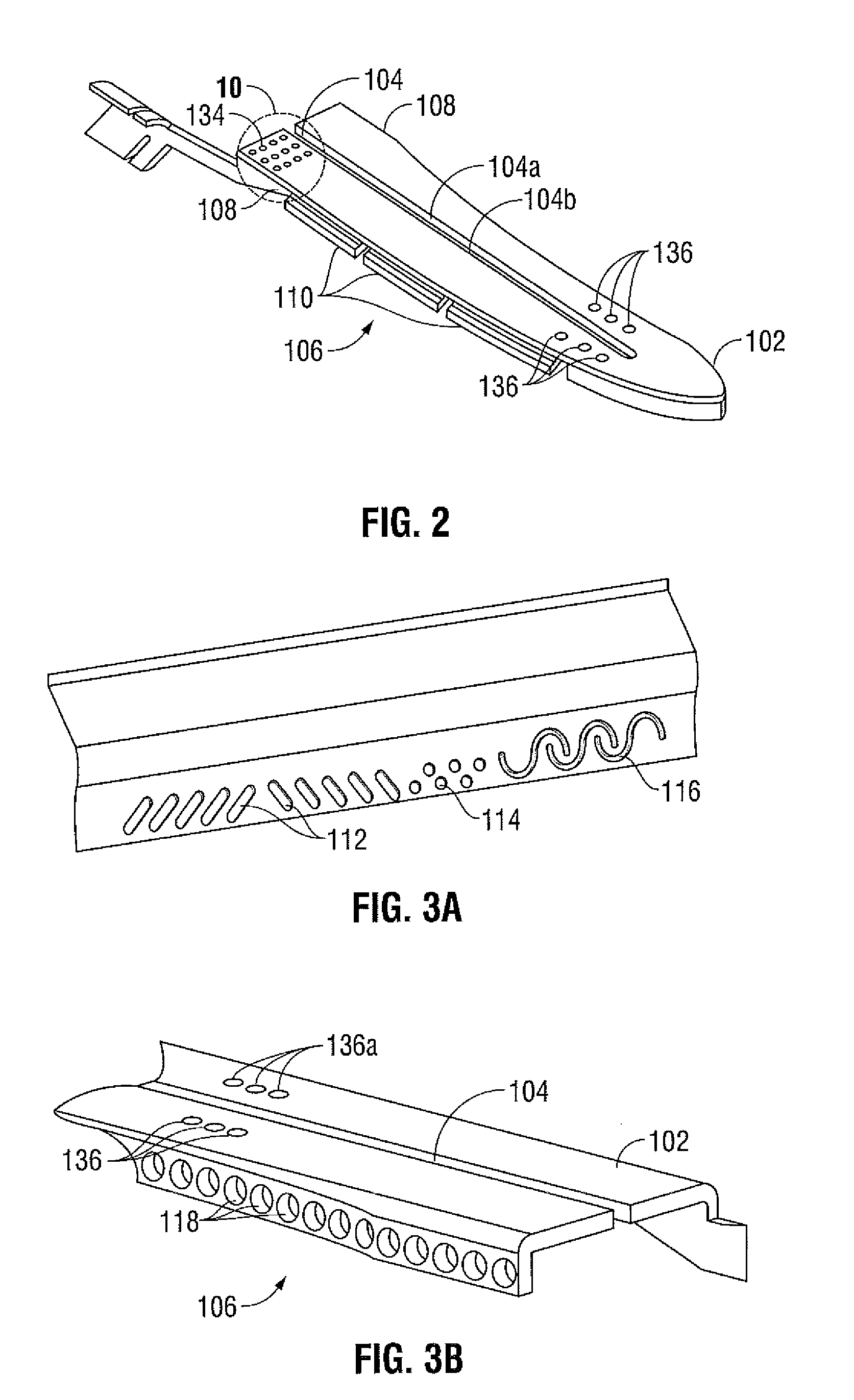
[0032]The method and system of the present disclosure implements photolithographic processes in combination with etching processes to create specific, unique, complex geometries and / or features for seal plates used in the design of electrosurgical instruments, such as, for example, bipolar and monopolar electrosurgical devices. For example, possible features may include knife blade slots, recessed features, fine delicate features, and half etched features; all of which to be discussed in greater detail below. In addition to creating the aforementioned features, the precision of etching allows for greatly reduced tolerance stack...


PUM

PropertyMeasurementUnit
etch depthaaaaaaaaaa
distanceaaaaaaaaaa
heightaaaaaaaaaa

Abstract

A method of manufacture for an end effector assembly is provided. The method includes providing a pair of jaw members. A step of the method includes forming one or more seal plates positionable on one of the pair of jaw members. Etching a dam along a side of the one or more seal plates is a step of the method, wherein the etched dam inhibits the flow of a plastic on the one or more seal plate such that a height of the plastic with respect to the at least one seal plate during an overmolding process may be controlled. The method includes positioning the one or more seal plates on the one of the pair of jaw members; and overmolding the seal plate to one or more of the pair of jaw members.

Description

BACKGROUND[0001]1. Technical Field[0002]The present disclosure relates to a method and system for manufacturing electrosurgical seal plates and, more particularly, to a method and system that employs photolithographic processes and systems operatively associated therewith to manufacture seal plates.[0003]2. Background of Related Art[0004]Electrosurgical forceps, e.g., bipolar or monopolar forceps, are commonly known in the medical art. Typically, the electrosurgical forceps are configured to, amongst other things, grasp and subsequently seal tissue. With this purpose in mind, the electrosurgical forceps, typically, include a pair of movable jaw members each having a respective seal plate operatively disposed thereon.[0005]Typically, the seal plates disposed on the jaw members are configured to transfer electrosurgical energy having one or more frequencies to tissue to electrosurgically treat the tissue (e.g., seal tissue) and, in conjunction with a cutting element (e.g., knife blade...

Claims


Application Information

Patent Timeline
Patent Type & Authority Patents(United States)
IPC IPC(8): H01S4/00
CPCA61B18/1445B32B38/10B32B38/0036B32B37/12A61B18/00C23F1/02Y10T29/5313B32B2535/00B32B2311/12B32B2038/0076Y10T29/49204Y10T29/49002Y10T29/49208Y10T29/49117A61B2017/00526
Inventor BRANDT, KIM V.AQUINO, ALLAN G.
Owner TYCO HEALTHCARE GRP LP
Why Eureka
Try Eureka