Flood prevention system and associated method

Inactive Publication Date: 2012-02-14
TALLMAN ERIC
View PDF11 Cites 6 Cited by
  • Summary
  • Abstract
  • Description
  • Claims
  • Application Information

AI Technical Summary

Benefits of technology

[0023]The lever thereby operates as a backup system, necessary should any problem occur with the electrical components of the valve or the power source. The automatic water flow preventing mechanism further may include a display panel situated within the housing and may be communicatively coupled to the controller. The display panel may provide a visual signal that indicates a real-time position of the restrictor valve such that a user can quickly and effectively determine whether the restrictor valve is open or closed. The display panel may employ indicia or light emitting diodes of various colors to quickly inform the user of the valve's status.
[002

Problems solved by technology

Ruptured water lines and malfunctioning equipment connected to water lines can result in serious flooding to the interior of a building or home.
The flooding generally occurs when the equipment or building is unoccupied by anyone who can detect the accumulation of water and shut off the water supply to the building.
Unfortunately, this prior art reference does not provide a manual means for togglin

Method used


Image

  • Flood prevention system and associated method
  • Flood prevention system and associated method
  • Flood prevention system and associated method

Examples


Example

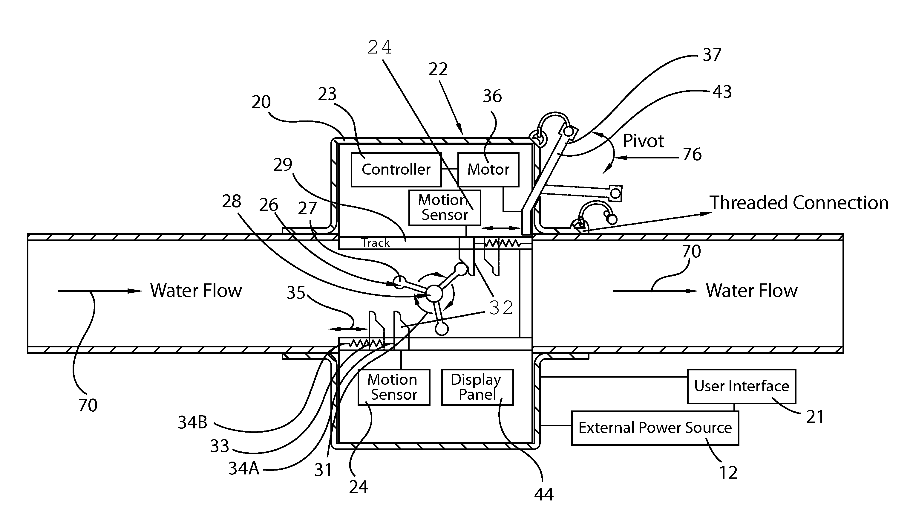
[0033]The present invention will now be described more fully hereinafter with reference to the accompanying drawings, in which a preferred embodiment of the invention is shown. This invention may, however, be embodied in many different forms and should not be construed as limited to the embodiment set forth herein. Rather, this embodiment is provided so that this application will be thorough and complete, and will fully convey the true scope of the invention to those skilled in the art. Like numbers refer to like elements throughout the figures.

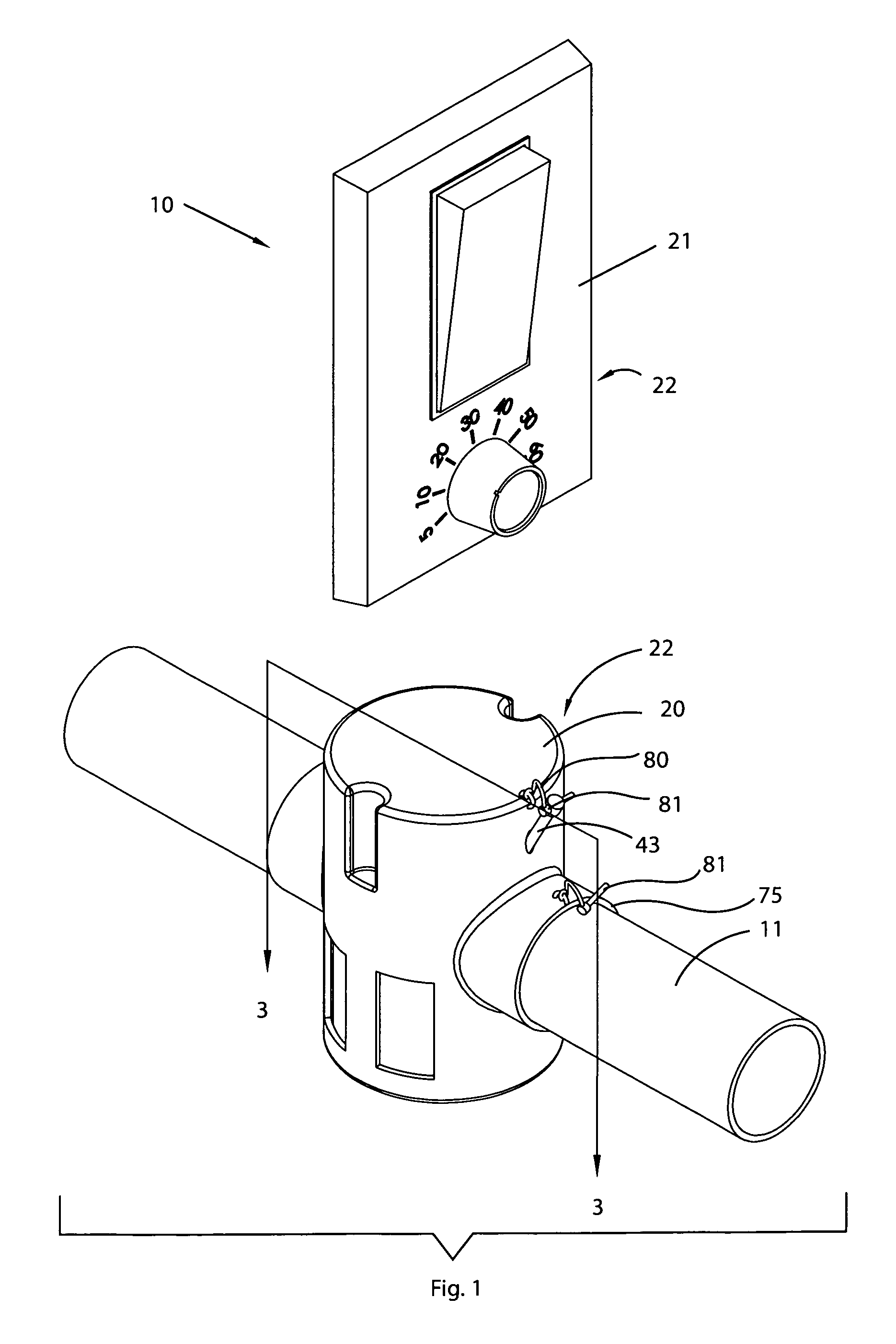
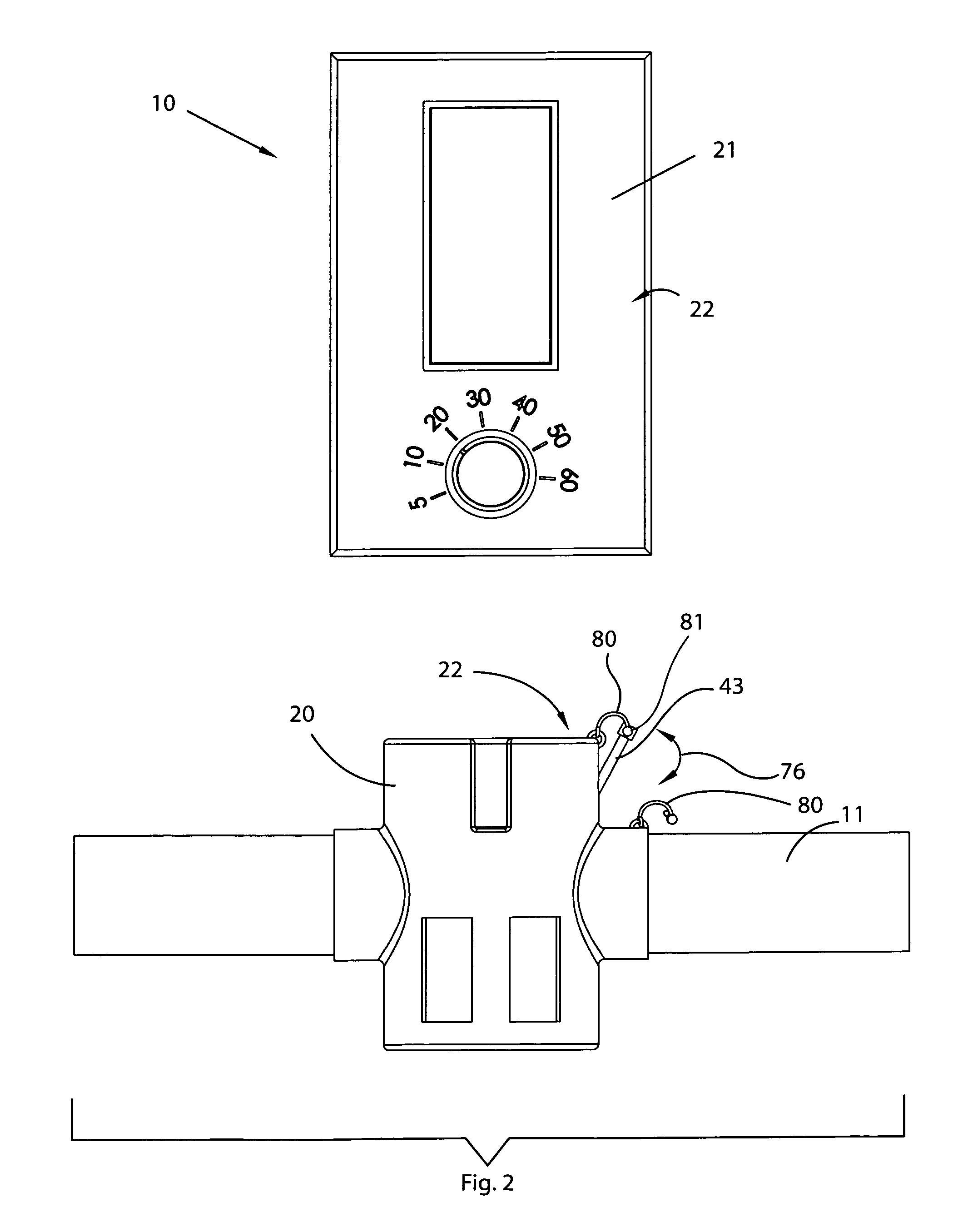
[0034]The system of this invention is referred to generally in FIGS. 1-4 by the reference numeral 10 and is intended to provide a water flow control system. It should be understood that the system 10 may be used for regulating water traveling through many different types of existing water supply lines and should not be limited in use to the applications mentioned herein.

[0035]Referring initially to FIGS. 1-3, a water flow control system 10 fo...


PUM


Abstract

A water flow control system for regulating water traveling through an existing water supply line preferably includes a housing connected to an existing water line. A user interface may be coupled thereto and remotely attached. A mechanism may automatically prevent water from flowing through the housing upon detection of a triggering event. A controller may be situated within the housing along with motion sensors. A rotatable fan may be situated within the housing along with a plurality of tracks, triggers, and resilient spring members anchored to the triggers and tracks respectively. The rotation speed of the fan may be commensurate with the real-time water flow rate of the water flowing through the housing. A control logic algorithm operates to close a restrictor valve if the water flow rate exceeds limits set by the user interface. A manually-actuated lever may also be attached to open or close the restrictor valve.

Description

CROSS REFERENCE TO RELATED APPLICATIONS[0001]This application claims the benefit of U.S. Provisional Application No. 60 / 963,459, filed Aug. 6, 2007, the entire disclosures of which are incorporated herein by reference.STATEMENT REGARDING FEDERALLY SPONSORED RESEARCH OR DEVELOPMENT[0002]Not Applicable.REFERENCE TO A MICROFICHE APPENDIX[0003]Not Applicable.BACKGROUND OF THE INVENTION[0004]1. Technical Field[0005]This invention relates to water valves and, more particularly, to a water flow control system for regulating water traveling through an existing water supply line.[0006]2. Prior Art[0007]Ruptured water lines and malfunctioning equipment connected to water lines can result in serious flooding to the interior of a building or home. The flooding generally occurs when the equipment or building is unoccupied by anyone who can detect the accumulation of water and shut off the water supply to the building. Because it is not always possible to have a person supervising equipment or wi...

Claims


Application Information

Patent Timeline
IPC IPC(8): F16K17/00
CPCE03B7/071G01F1/06G01F15/003Y02A20/15Y10T137/7786Y10T137/7727
Inventor TALLMAN, ERIC
Owner TALLMAN ERIC
Why Eureka
Try Eureka