Grinding worm, profiling gear and process for the profiling of the grinding worm

a technology of grinding worm and profiling gear, which is applied in the direction of grinding machines, gear teeth, other manufacturing equipment/tools, etc., can solve the problems of small number of workpieces that can be ground, residual deviations, and workpieces with such tooth flank modifications cannot be produced within limits, so as to increase the degree of worm exploitation, shorten the profiling time, and alter the degree of flexibility

Active Publication Date: 2012-02-14
REISHAUER AG
View PDF59 Cites 13 Cited by
  • Summary
  • Abstract
  • Description
  • Claims
  • Application Information

AI Technical Summary

Benefits of technology

[0009]The object of the invention is therefore to provide a grinding worm with at least one arbitrarily three-dimensionally modified width zone, which said grinding worm affords an increased degree of exploitation of its worm width, where the flank geometry of the workpiece to be machined with this grinding worm can be altered more flexibly in production, and the profiling time nevertheless be kept short.
[0010]The grinding worm according to the invention is provided with at least one width zone for finishing and one width zone for roughing, which are arranged to mutually merge or overlap axially. The transition zone between the roughing and finishing zones is thereby minimized. The usable zone of the grinding worm is increased and the profiling time minimized.
[0014]Due to the particular design of the profiling gear, the flank geometry of the workpiece to be ground can be varied or corrected and the surface roughness of the grinding worm flanks adapted optimally to the demands of rough and finish grinding, without altering the flank geometry of the profiling gear.
[0015]In a preferred embodiment the profiling gear according to the invention has profiling width zones of differently shaped flank modifications. This profiling gear is preferably employed in the process according to the invention, by which the flank geometry of individual width zones of the profiling gear is transferred section for section to selected grinding width zones of the grinding worm by means of appropriate mutually allocated axial profiling strokes of the grinding worm and the profiling gear. This permits the flank geometry and surface roughness of the grinding worm zones to be produced individually according to their purpose.
[0017]By suitable selection of the diagonal ratio and the allocation of the width zones of the profiling gear to the grinding width zones of the grinding worm when profiling, it becomes possible, as mentioned above, to adapt the modifications of the grinding worm flanks to the needs of the workpiece without having to alter the flank geometry of the profiling gear.

Problems solved by technology

With the familiar methods and tools applied in generation grinding with a cylindrical grinding worm, workpieces with such tooth flank modifications can only be produced within limits, i.e. with considerable residual deviations or very extensive profiling resources.
A disadvantage of this solution is the residual deviations that occur due to the arc shaped locus of the path of contact between grinding worm and workpiece tooth flank in conjugate reproduction.
A further disadvantage is the small number of workpieces that can be ground per grinding worm profiling operation.
For since the modified grinding worm zone is used both for rough and for finish grinding, the high wear suffered during rough grinding has a negative effect on the ultimate accuracy.
On account of the given fixed profile of the profile roll, however, a considerable loss in usable grinding worm width is incurred at the transition between the rough and the finish grinding zone.
The disadvantage of these solutions lies chiefly in the necessarily long profiling times, so that they may be suitable for small and medium series, but not for large series production.
One of the disadvantages of profiling a grinding worm with a profiling gear lies in the fact that when manufacturing the workpieces the workpiece flank geometry can only be altered slightly or not at all.
This disadvantage and the high cost of a profiling gear makes the profiling of a grinding worm with a profiling gear only economical in large series production, where the desired workpiece geometry remains constant over long manufacturing periods, and the long life of an abrasive coated profiling gear can be fully exploited.

Method used


Image

  • Grinding worm, profiling gear and process for the profiling of the grinding worm
  • Grinding worm, profiling gear and process for the profiling of the grinding worm
  • Grinding worm, profiling gear and process for the profiling of the grinding worm

Examples


Embodiment Construction

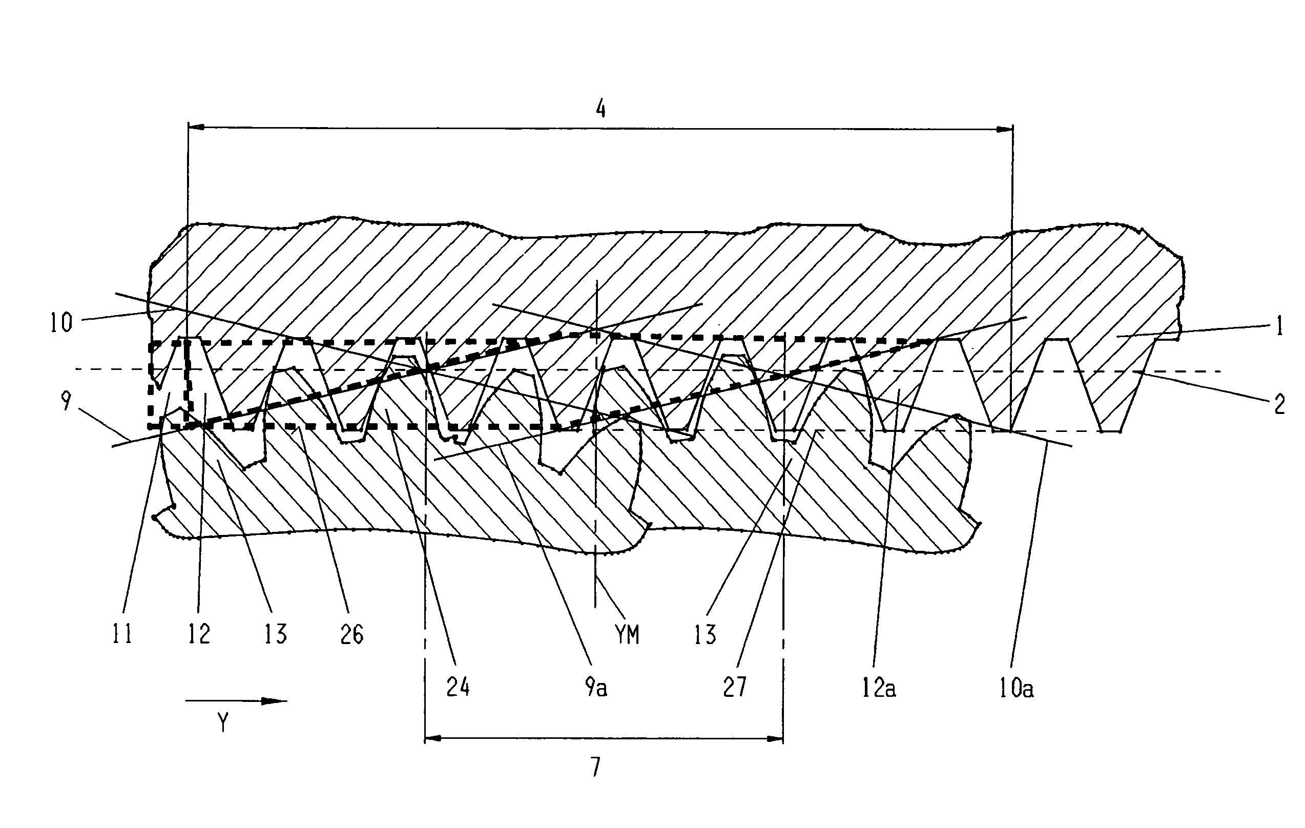
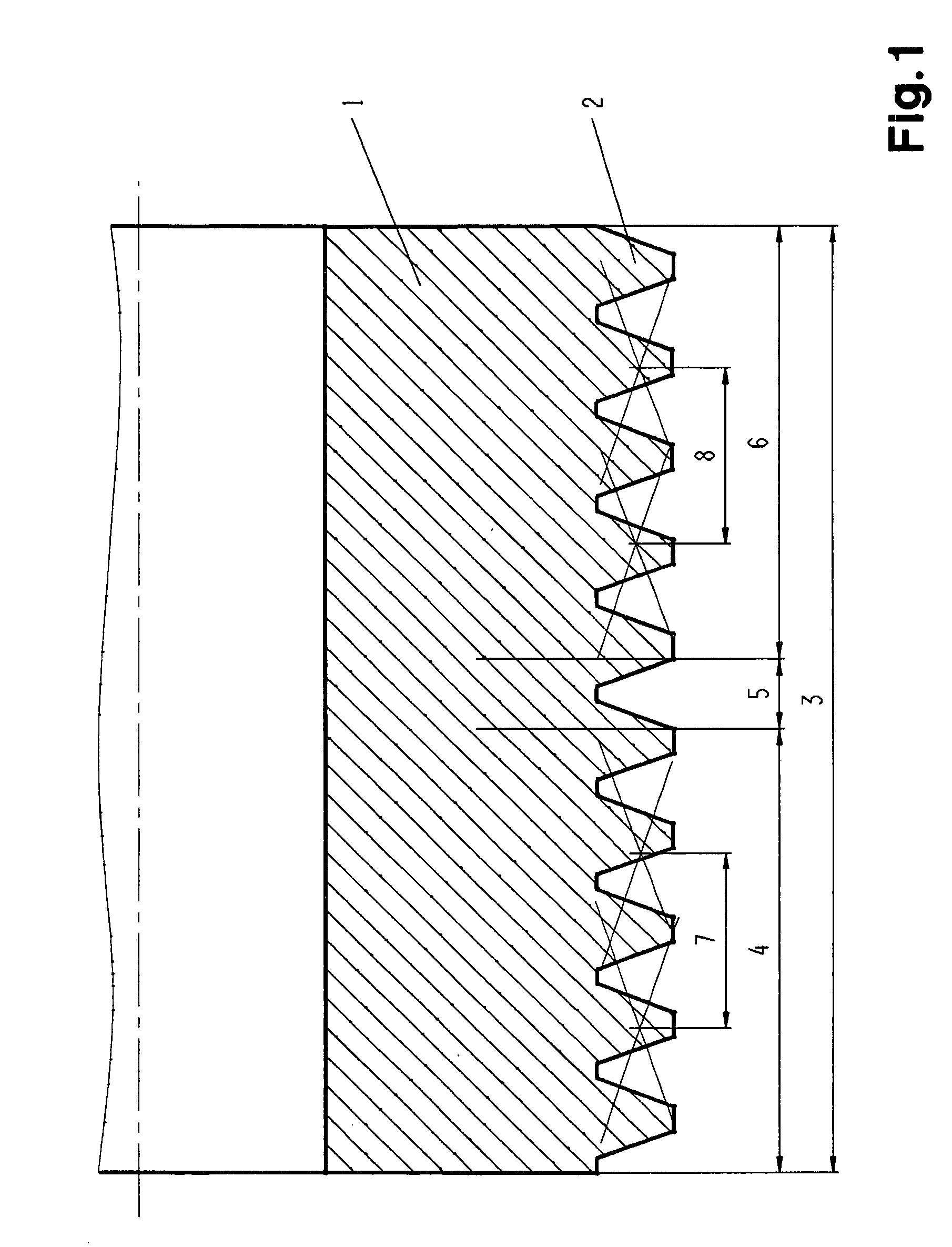
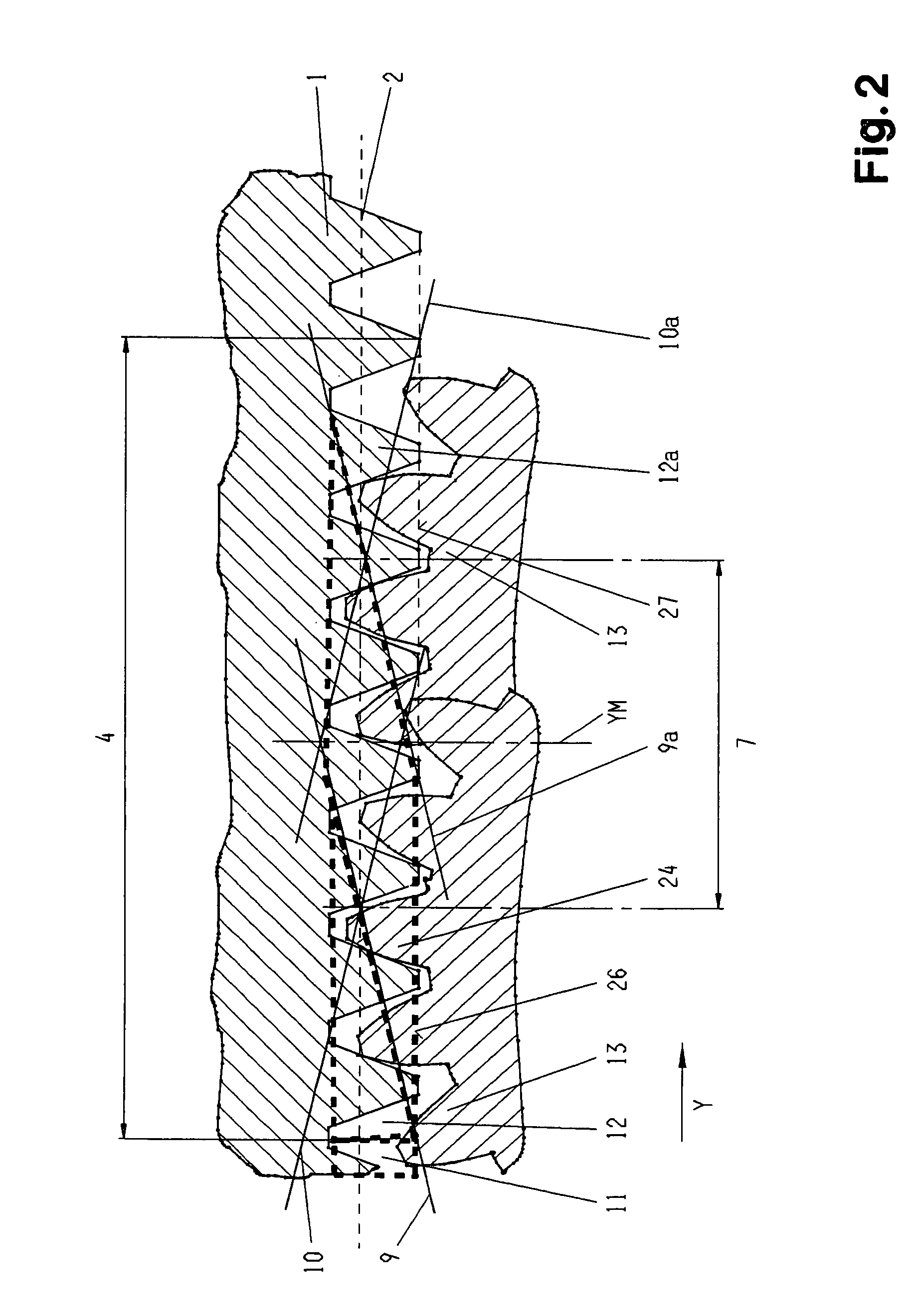
[0036]In the FIGS. 1, 2a and 2b a part of a grinding worm is depicted such as corresponds with the background of the invention and such as is used for the continuous generation grinding of workpieces, in particular of the teeth of cylindrical spur and helical gears. It can be employed singly, or several grinding worms can be arranged coaxially one behind the other.

[0037]The grinding worm 1 is provided with a single or multi-start grinding worm profile 2 of cylindrical basic geometry. It has a total zone with a total width 3, the total zone being divided into a rough grinding zone 4, a transition zone 5 and a finish grinding zone 6.

[0038]It is also possible to employ separate grinding worms for rough grinding and for finish grinding. In this case the width of the rough grinding worm corresponds with the rough grinding zone width 4, and the width of the finish grinding worm with the finish grinding zone width 6. The distance between the rough and the finish grinding worms represents t...


PUM

PropertyMeasurementUnit
lengthaaaaaaaaaa
widthaaaaaaaaaa
roughing shift widthaaaaaaaaaa

Abstract

A grinding worm for the continuous generation grinding of a work piece is provided with mutually overlapping rough grinding and finish grinding zones arranged along the worm's axis, the finished grinding zone being provided with a three-dimensionally modified flank geometry having a width related design.

Description

FIELD OF THE INVENTION[0001]The invention concerns a grinding worm and a profiling gear, together with a process for the profiling of the grinding worm.BACKGROUND OF THE INVENTION[0002]In gear drive engineering the efforts to increase the power concentration and reduce noise emission of the gear units are leading more and more to gears units and individual gears with three-dimensionally, i.e. topologically modified tooth flanks. Thanks to such modifications, favourable tooth bearing and dynamic response behaviour of gear pairs in mesh can be achieved, although their tooth deformation alters under the variable loading. As a result of these efforts, gears are calculated, designed and manufactured which are provided with complex tooth flank modifications, e.g. in the form of tip and root relief, or of undulations which run parallel to the lines of contact of a gear pair.[0003]With the familiar methods and tools applied in generation grinding with a cylindrical grinding worm, workpieces...

Claims


Application Information

Patent Timeline
Patent Type & Authority Patents(United States)
IPC IPC(8): B24B1/00B23F21/02B23F21/23B24B53/075B24D5/00B24D18/00
CPCB23F21/026B23F23/1231Y10S451/90
Inventor JANKOWSKI, RALFSCHMID, ROLANDNOBS, DIETERSIEBERT, MICHAELTHYSSEN, WOLFGANG
Owner REISHAUER AG
Why Eureka
Try Eureka