
Low-profile pathway illumination system

a low-profile, pathway technology, applied in the direction of lighting support devices, pathways, instruments, etc., can solve the problems of high installation and maintenance costs, sensors and timers, and high cost of electronic control, so as to minimize collision and tripping danger, easy and less expensive to install and replace, and low profile

Inactive Publication Date: 2012-02-21
EXPRESS IMAGING SYST
View PDF58 Cites 56 Cited by
  • Summary
  • Abstract
  • Description
  • Claims
  • Application Information

AI Technical Summary

Problems solved by technology

Overhead and bollard lighting systems are typically robust and permanent, but tend to have relatively high costs of installation and maintenance.
These lighting systems are typically powered by the mains voltage and typically require expensive waterproof conduits, concrete support bases and careful planning to install.
Besides, the electronic controls, sensors and timers required for their operation are expensive and must be installed by licensed electricians.
Overhead and bollard lighting systems also tend to detract from the aesthetics of the architecture, landscaping and natural features where they are sited.
In some cases, both the luminaires and the light they emit block the view of the carefully designed environment that they are lighting, and greatly detract from the visual enjoyment of the site.
These near-ground lighting systems, however, may be less robust as they tend to suffer from the small size of their mountings.
Maintenance costs associated with these small, near-ground lighting systems can be high because of the large number of lamps that eventually need replacement, physical damage to the more delicate luminaires, and the close proximity of the luminaires to lawn maintenance equipment and pathway traffic.
While aesthetically more pleasing than overhead lights or bollards, these near-ground lighting systems also detract from a well-designed space, cluttering the pathway with fragile-looking luminaires.
These lights tend to be difficult to install and maintain because they are designed to be embedded in the pathway surface material.
Installation is especially difficult and expensive if paver lights are to be installed into existing concrete sidewalks.
Additionally, power wires must be run under the pathway, further making them difficult and expensive to install and maintain.
Worse yet, paver lights may obscure the presence of potential hazards by shining upwards into a pedestrian's eyes.
In the case of overhead or bollard lights, a very real danger exists of collision from riding lawn mowers, maintenance trucks and carts, or from individuals engaged in sports or other activities.
Near-ground pathway lights are very costly to mow or weed around, and may easily be damaged in the process.
They also present a hazard to pedestrians who may trip over or onto the relatively short luminaires.

Method used


Image

  • Low-profile pathway illumination system
  • Low-profile pathway illumination system
  • Low-profile pathway illumination system

Examples


Embodiment Construction

[0022]In the following description, certain specific details are set forth in order to provide a thorough understanding of various disclosed embodiments. However, one skilled in the relevant art will recognize that embodiments may be practiced without one or more of these specific details, or with other methods, components, materials, etc. In other instances, well-known structures associated with lighting fixtures, power generation and / or power systems for lighting have not been shown or described in detail to avoid unnecessarily obscuring descriptions of the embodiments.

[0023]Unless the context requires otherwise, throughout the specification and claims which follow, the word “comprise” and variations thereof, such as “comprises” and “comprising,” are to be construed in an open, inclusive sense that is as “including, but not limited to.”

[0024]Reference throughout this specification to “one embodiment” or “an embodiment” means that a particular feature, structure or characteristic d...


PUM


Abstract

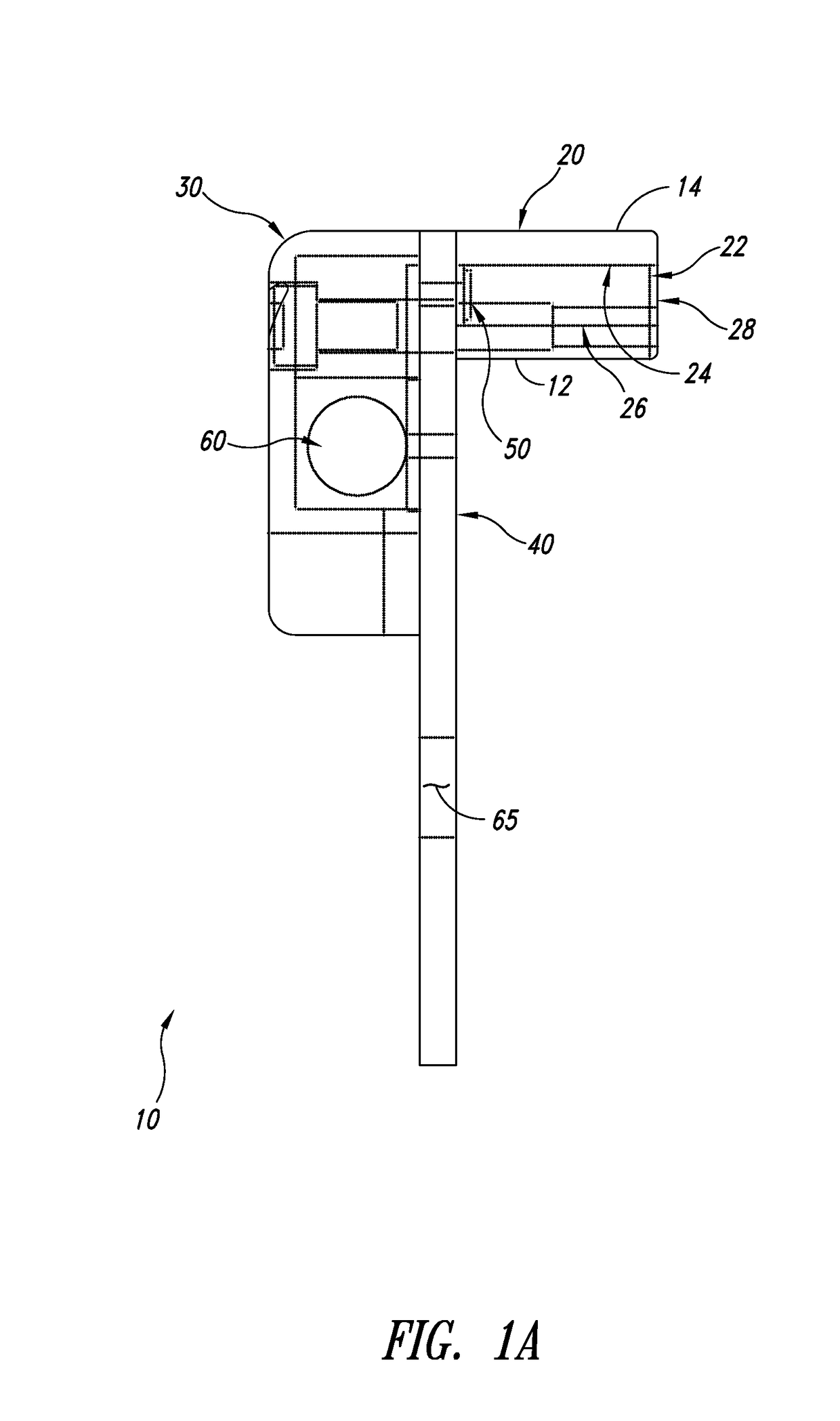
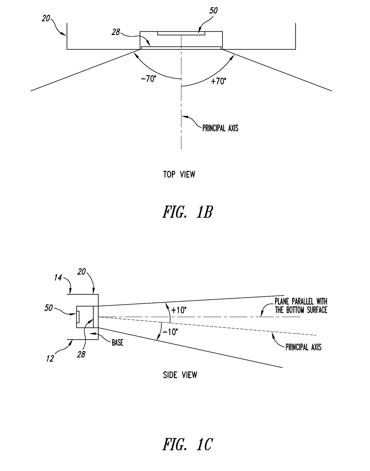
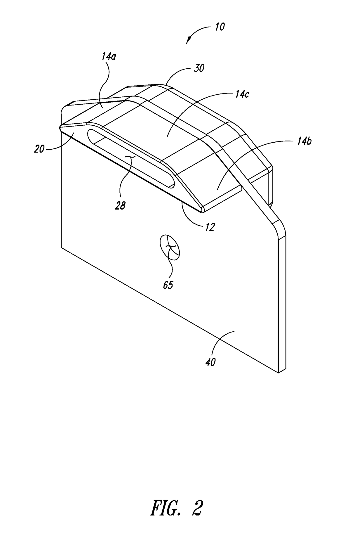
A luminaire to illuminate surfaces comprises a housing, a mounting fixture and a light source. The housing includes a base having a bottom surface positionable on a surface to be illuminated, an interior, and at least one window providing access between the interior and an exterior of the housing. The mounting fixture extends at least approximately perpendicularly downward with respect to the bottom surface of the base to secure the housing into a peripheral portion of the surface to be illuminated. The light source has a principal axis of emission that is directed outwardly through the window of the housing at a downwardly oriented angle with respect to the bottom surface of the base such that, when in use with the luminaire mounted to the surface to be illuminated, the principal axis of emission of the light source is directed at a portion of the surface to be illuminated.

Description

CROSS-REFERENCE TO RELATED APPLICATION[0001]This application claims the benefit under 35 U.S.C. §119(e) of U.S. Provisional Patent Application Ser. No. 61 / 051,619, filed May 8, 2008, entitled “Low-Profile Pathway Illumination System”, which is incorporated herein by reference in its entirety.BACKGROUND[0002]1. Technical Field[0003]This disclosure generally relates to an illumination system and more particularly to a low-profile pathway illumination system.[0004]2. Description of the Related Art[0005]Pathway lighting is important for safety and security reasons and, in some cases, for aesthetic reasons as well. In general, existing pathway lights can be grouped into three main classes: bollards and overhead lighting systems that are installed on poles or walls, lighting systems mounted close to the ground, and “paver lights” installed in a pathway surface. Further, pathway lights can be divided into low voltage and mains voltage lighting systems.[0006]Overhead and bollard lighting sy...

Claims


Application Information

Patent Timeline
Patent Type & Authority Patents(United States)
IPC IPC(8): F21V3/00
CPCE01F9/065F21S8/032F21S8/022F21W2111/023F21W2131/109F21Y2101/02E01F9/559F21Y2115/10
Inventor REED, WILLIAM G.RENN, JOHN O.
Owner EXPRESS IMAGING SYST
Learn More