Firearm with enhanced recoil and control characteristics

a control characteristic and recoil technology, applied in the field of small and heavy caliber firearms and machine firearms, can solve the problems of affecting accuracy and the effectiveness of automatic weapons, operators were susceptible to explosive forces, and the effect of accuracy and ease of use, so as to reduce the vibration of the slider, reduce the vibration of the operation, and reduce the effect of vibrational movemen

Active Publication Date: 2012-02-28
KRISS SYST
View PDF4 Cites 16 Cited by
  • Summary
  • Abstract
  • Description
  • Claims
  • Application Information

AI Technical Summary

Benefits of technology

[0019]The recoil control device's components can be advantageously prepared with comparatively large parts or large diameter spindles or rods, which simplifies manufacture. This advantage of the present invention greatly improves the reliability in service and the resistance to jamming by sand, mud, and other environmental contaminants and simplifies cleaning and dismantling of the firearm.
[0020]The mechanisms and aspects of the invention can be used to complement or improve existing or conventional firearms and can be combined with various arrangements, attachments, and combinations, including without limitation internal release systems, loading systems, ejection systems, gas injection systems, recoil reduction systems, muzzle brakes, sighting systems, tripods, mounting systems, and firing mechanisms.
[0021]In one general aspect, the invention comprises an improved and novel recoil control device for use in a firearm, such as a semiautomatic or automatic firearm, in which, for example, a bolt head is configured to alternate between a forward position and a rearward position in response to the firing of one or more cartridges; and an inertia block is connected to the bolt head such that the bolt head imparts an impulse to the inertia block as it alternates between its forward position and its rearward position, the impulse having a component, or force distribution or vectorial force component, lateral to the firing axis of the barrel of the firearm. The force transferred to the inertia block can be in any one of several directions and the inertia block can therefore traverse one of a variety of paths from the impulse imparted through the bolt head, including, but not limited to: a downward sloping, straight path toward the anterior of the firearm; a curved or curvilinear path; a path extending outward from the barrel; a path moving inward toward the barrel; and a path crossing over the barrel. The path chosen relates to the design characteristics of the firearm desired.
[0022]Similarly, the inertia block or mass appropriate for a particular firearm relates to the design characteristics of the firearm. In one embodiment, the inertia block comprises a sloped or angled surface, or a leading sloped surface, that can be contacted by the bolt head to transmit the impulse from firing. In other embodiments, the inertia block comprises a part or parts that reciprocates between two or more positions and moves in response to the impulse from the bolt head. Multiple inertia blocks can also be used so that they move together in response to the bolt head. In another preferred embodiment, the recoil control device of the present invention can be incorporated into heavy caliber firearm and cannon mechanisms. For example, a heavy caliber rifle, such as a vehicle-mounted rifle or portable rifle of between .50 caliber and 105 mm, or even higher as in a 155 mm cannon, can be produced with an inertia block to translate forces out of the axis of the barrel. In still other embodiments, the recoil control device can be incorporated into a shotgun or automatic shotgun.
[0023]The transfer of the impulse of percussion from the bolt head to the inertia block can be through direct contact between the two parts or through a simple or even a complex linkage. In one embodiment, one or more pin and rod assemblies are used. In another embodiment, a pin connected to the bolt head moves within a slot connected to the inertia block. In other embodiments, one or more reciprocating rods connect the bolt head to the inertia block. In one embodiment, the slider is designed to oscillate during its movement and interact with a roller or recoil dampening point in the receiver. In another embodiment, the design of the bolt, slider and guides in the receiver or housing are specifically designed to reduce, and optionally reduce to a substantial degree, the oscillation or vibration of the slider during its movement. Multiple interactions between the bolt and the slider, additional guides for controlling the slider, and optionally a buffer assembly incorporated into the slider to interact with a fixed element at the terminal end of the slider movement, can each reduce vibration in the operation. A reduction in the vibrational movement of the slider can advantageously improve the operation of a firearm in general and the serviceable life of certain parts.
[0024]For most firearms of the invention, the inertia block and bolt head are designed to automatically return to their resting or chambered position. A variety of mechanisms can be used to move the bolt head and / or inertia block in the return path. A preferred embodiment employs a spring operably connected to or contacting the inertia block, which can be referred to as the return spring. A variety of spring types can be adapted for this purpose. Alternative return or recovery mechanisms can be designed by one of skill in the art.

Problems solved by technology

However, the rapid firing of successive cartridges induces various side effects that proved detrimental both to accuracy and the effectiveness of an automatic weapon.
Throughout the time these improvements were made a main issue was safety.
Depending on the design, operators were susceptible to explosive forces from an improperly chambered round or an incomplete breech lock on the chambered round.
A common but unsatisfactory feature among all these mechanisms is that they do not prevent the undesirable side effects during automatic firing, which accounts for the adverse effects on accuracy and ease of use.
Thus, the mechanisms found on current firearms, although reliable and widely employed, nevertheless suffer from a number of deficiencies.
For example, some mechanisms increase the length of the housing of the breech, resulting in interior clutter and increased weight.
The amplitude of recoil is relatively critical due to its effect on accuracy, and the existing mechanisms fail to provide a satisfactory or optimum reduction in recoil, which permits the resulting upward movement of the barrel—muzzle climb or muzzle rise.

Method used


Image

  • Firearm with enhanced recoil and control characteristics
  • Firearm with enhanced recoil and control characteristics
  • Firearm with enhanced recoil and control characteristics

Examples


Embodiment Construction

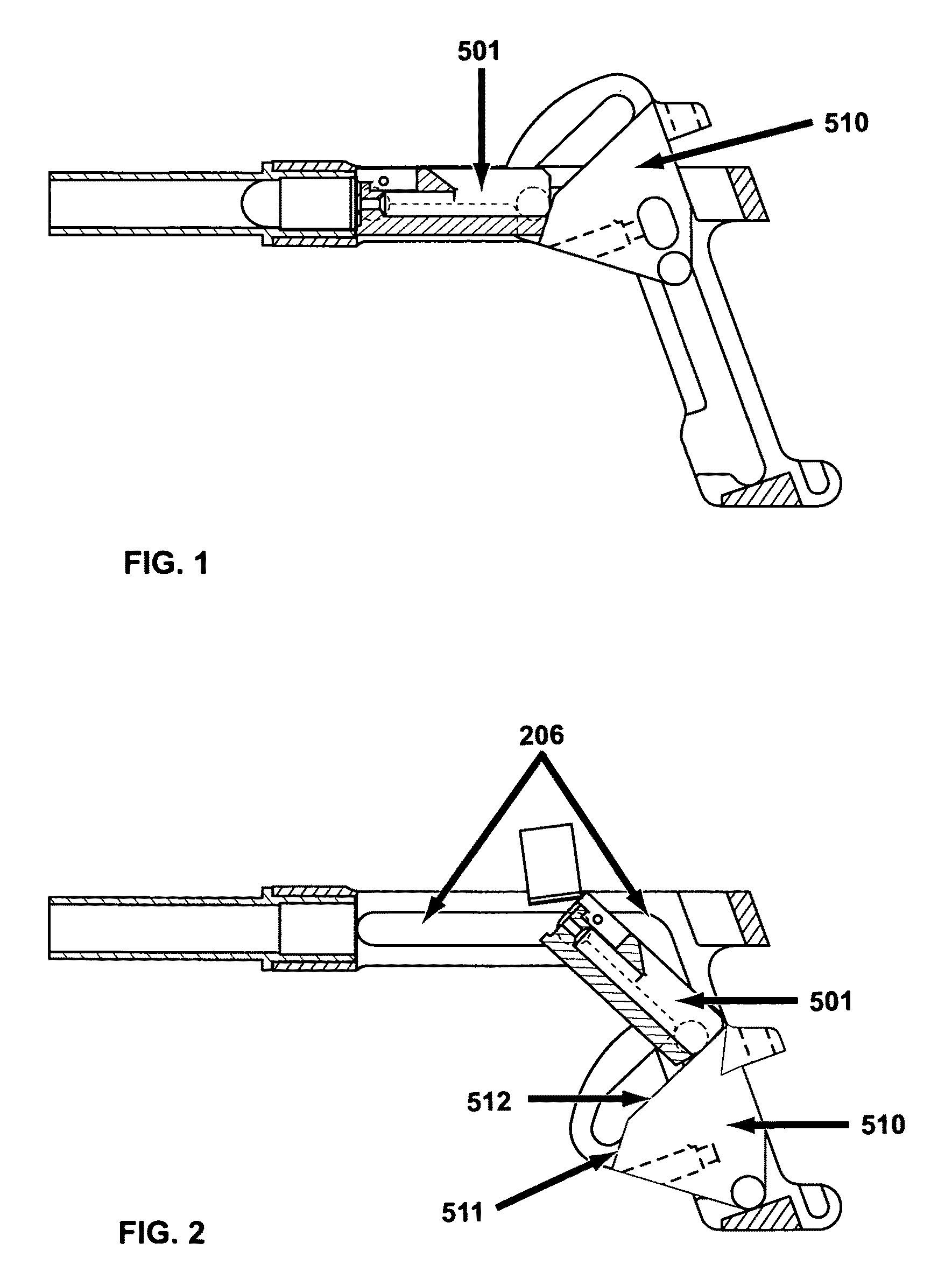
[0068]Whether for handguns or rifles, in other words pistols, machine pistols, shotguns, rifles, and assault rifles, the present invention advantageously reduces the consequences of recoil and / or eliminates, for all practical purposes, a weapon's reactive jerking and permits a more compact weapon for a given caliber ammunition.

[0069]Where heavy firearms are concerned, for example machine guns and cannons, notably machine guns for land, water craft, or airborne platforms, the present invention enables a lighter frame for the weapon and a more compact and therefore more stowable or containable weapon. This allows moveable weapon systems to store more ammunition per sortie. Further, this invention enables a simplified construction for the base by diminishing the recoil tendency and dampening the stress acting upon the platform as a whole.

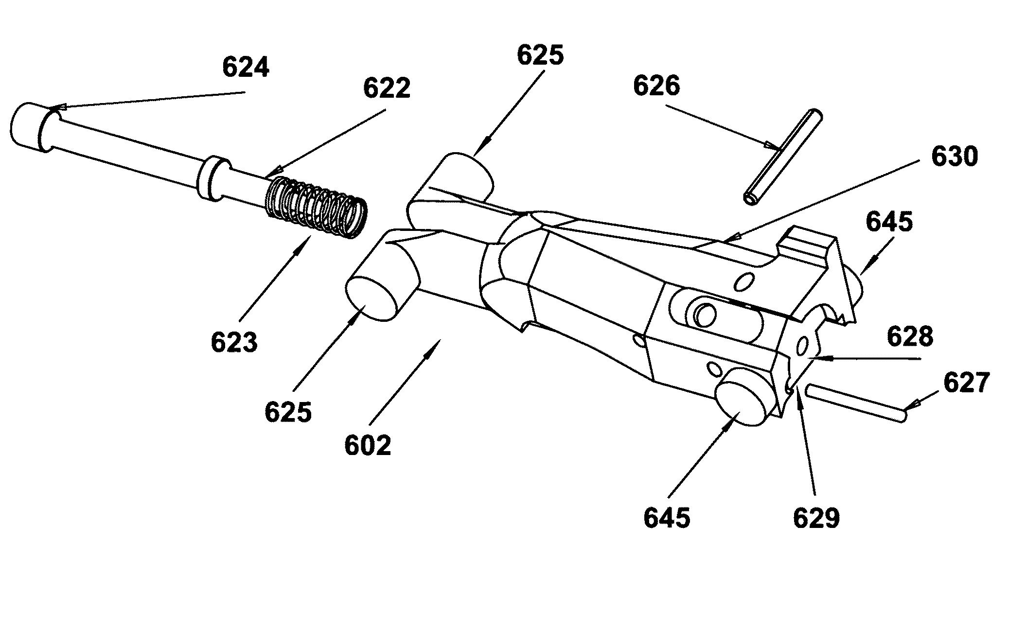
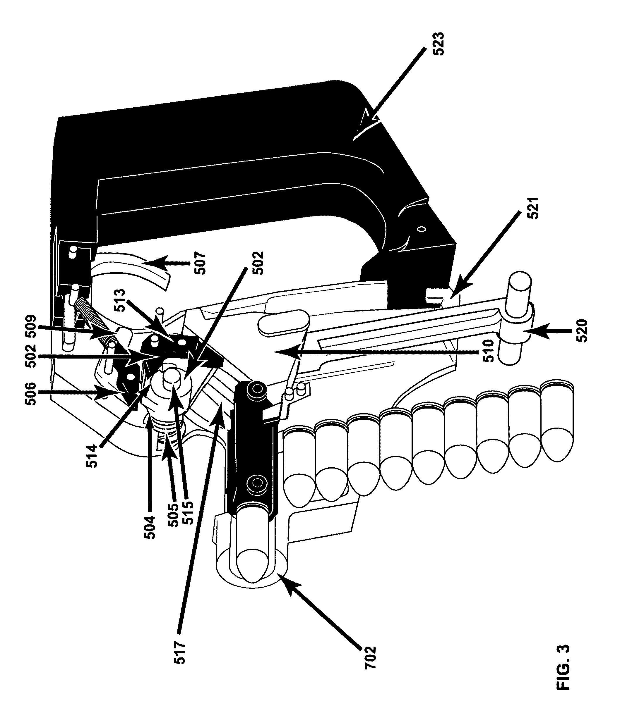
[0070]In one particular embodiment, the invention comprises a mobile breech made up of connected parts that comprise an inertia block and a bolt head....


PUM


Abstract

The invention comprises improved designs in a recoil control device comprising a bolt and slider for use in a variety of firearms. In one embodiment, the bolt and slider are articulated so that the displacement of the bolt results in a force component accompanying the slider as it moves along a slider path that traverses a line formed by a linear firing axis of the barrel of the firearm. The slider can have additional structural and functional features, including stabilizing features, vibrational damping elements, elements of the fire control mechanism, and devices to manage the peak impulse of the slider movement as it contacts a base or terminus point.

Description

RELATED APPLICATIONS[0001]This application claims priority benefit to U.S. Provisional application 60 / 879,530, filed Jan. 10, 2007, and priority benefit of U.S. application Ser. No. 11 / 783,380, filed Apr. 9, 2007, now U.S. Pat. No. 7,997,183, which is a continuation of Ser. No. 10 / 454,780, filed Jun. 5, 2003 (now U.S. Pat. No. 7,201,094), and priority benefit of pending U.S. application Ser. No. 10 / 454,778, filed Jun. 5, 2003, each of which claim priority benefit to U.S. Provisional Application No. 60 / 459,969, filed Apr. 4, 2003, and priority benefit of Swiss Application No. 0975 / 02, filed Jun. 7, 2002, Swiss Application No. 1343 / 02, filed Jul. 31, 2002, and Swiss Application No. 0679 / 03, filed Apr. 15, 2003. Each of the above-listed prior applications are specifically incorporated herein by reference in their entirety.FIELD OF INVENTION[0002]This invention relates to small and heavy caliber firearms and machine firearms as well as to improved methods and devices for reducing the co...

Claims


Application Information

Patent Timeline
Patent Type & Authority Patents(United States)
IPC IPC(8): F41A3/10
CPCF41A1/08F41A3/00F41A3/02F41A3/12F41A3/50F41A3/64F41A9/41
Inventor KERBRAT, RENAUDLINDSAY, TIMOTHY
Owner KRISS SYST
Why Eureka
Try Eureka