Rotor balancing system for turbomachinery

Inactive Publication Date: 2012-02-28
RAYTHEON TECH CORP
View PDF10 Cites 13 Cited by
  • Summary
  • Abstract
  • Description
  • Claims
  • Application Information

AI Technical Summary

Benefits of technology

[0007]Accordingly, it is an object of the present invention to provide a rotor b

Problems solved by technology

One of the deficiencies of the Tiernan, Jr. et al. construction is that the locating slots act similar to rotating blades, turning and heating up the air in the cavities as the rotor element rotates.
The mixture of hot cavity air and cooler flow path air reduces the overall fan efficiency.
Additionally, the air pumping (windage) caused by the locating slots forc

Method used


Image

  • Rotor balancing system for turbomachinery
  • Rotor balancing system for turbomachinery
  • Rotor balancing system for turbomachinery

Examples


Embodiment Construction

)

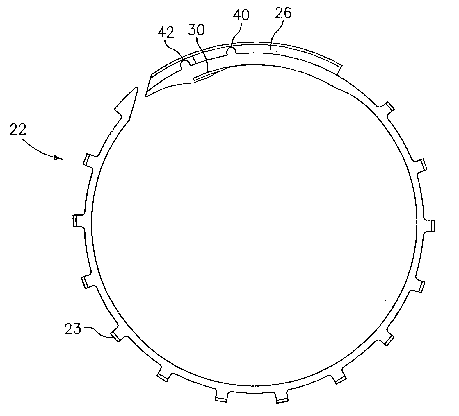
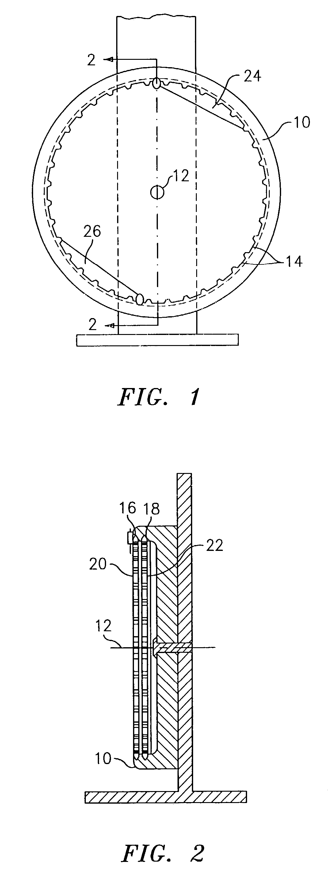
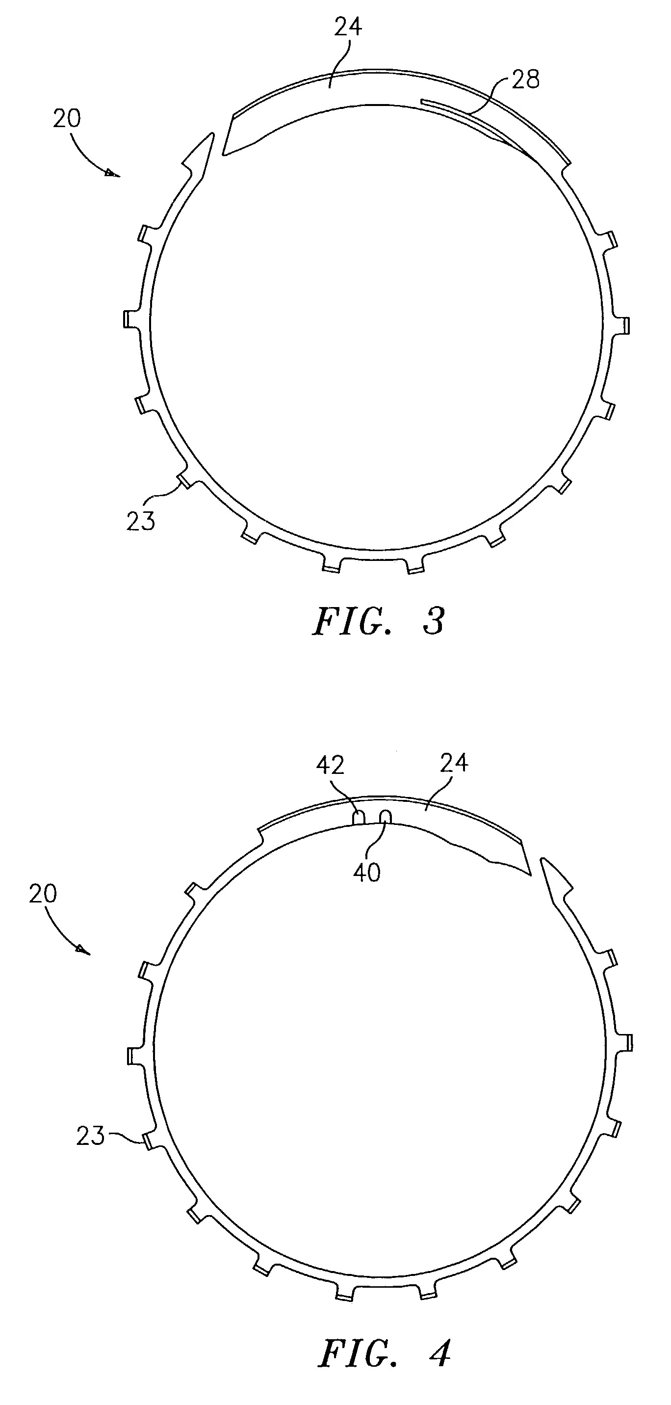
[0028]Referring now to the drawings, FIGS. 1, 2, and 9 illustrate an annular rotor element 10 having an axis 12 and a row of scallop shaped locating slots 14 about its inner circumference. The rotor element 10 contains two inner circumferential grooves 16 and 18. Positioned within each of the circumferential grooves is an annular counterweight balancing ring 20 and 22. Each of the counterweight balancing rings 20 and 22, as shown in FIGS. 3-6, has a split ring construction wherein a first end is spaced from a second end when said ring is in a relaxed state with the second ends of each balancing ring preferably having a weighted portion 24 and 26, respectively. Each ring 20 and 22 also has a plurality of teeth 23 for engaging the slots 14 (see FIGS. 3-6, and 8).

[0029]Each of the counterweight balancing rings 20 and 22 is rotatable within the circumferential grooves 16 and 18 when not engaged with one or more of the locating slots 14. To facilitate its proper positioning, the balanci...


PUM


Abstract

The present invention relates to an improved rotor balancing system which allows for fine tune onsite adjustment for turbomachinery. The rotor balancing system comprises a rotor element having a row of locating slots and a device for reducing windage effects caused by the locating slots and protruding anti-rotation pins. In a preferred embodiment, the device for reducing windage effects comprises at least one balancing ring which partially or fully covers the locating slots and internal slots for engaging and disengaging that does not protrude outbound of the ring. Each balancing ring is preferably provided with two integrally formed anti-rotation members for engaging the locating slots. Each balancing ring is also preferably provided with a slot in a weighted portion of the ring for receiving a tool for positioning the balancing ring in a desired position. A method for positioning the balancing ring on a rotor element using the slot and the tool is also described herein.

Description

CROSS-REFERENCE TO RELATED APPLICATION(S)[0001]This application is a continuation application of U.S. patent application Ser. No. 09 / 815,742, filed Mar. 23, 2001, now U.S. Pat. No. 6,588,298 entitled ROTOR BALANCING SYSTEM FOR TURBOMACHINERY, by Paul Czerniak et al.BACKGROUND OF THE INVENTION[0002]The present invention relates to a rotor balancing system for turbomachinery which safely secures balancing rings to a rotor element while reducing windage effects caused by locating slots on the rotor element and to a method for positioning a balancing ring on a rotor element.[0003]In rotating machinery, it sometimes becomes necessary to trim the balance of one of the rotor elements after the machinery has been initially balanced for assembly and has been operating in service. Typically, the machinery must be disassembled, completely or partially, to permit rebalancing or trim balancing of the offending rotor element. With aircraft gas turbine engines, it is desirable to be able to quickl...

Claims


Application Information

Patent Timeline
IPC IPC(8): F16F15/22F16F15/34
CPCF01D5/027F16F15/34Y10T74/2109Y02T50/673F05D2260/97Y02T50/671Y02T50/60
Inventor CZERNIAK, PAULRUBALCABA, DANIEL G.PRIVETT, JOHN D.
Owner RAYTHEON TECH CORP
Why Eureka
Try Eureka