Plunger piston made from plastic for an air spring

a technology of pneumatic springs and plastics, which is applied in the direction of springs, vibration dampers, gas based dampers, etc., can solve the problems of affecting the function reliability of the attachment, the difficulty of connection with known pneumatic springs, and the inability to meet the requirements of the application, and achieves cost-effective production and sufficient dimensional stability.

Inactive Publication Date: 2012-02-28
LKH KUNSTWERK
View PDF8 Cites 9 Cited by
  • Summary
  • Abstract
  • Description
  • Claims
  • Application Information

AI Technical Summary

Benefits of technology

[0009]It is one object of this invention to provide a plunger piston for a pneumatic spring which can be produced cost-effectively in a simple manner and still shows sufficient dimensional stability and thus provides protection against undesired deformations and the formation of cracks. Also, the plunger piston in accordance with this invention assures dependable transmission of forces and distribution of forces between the pneumatic spring bellows and the resilient component.
[0011]Accordingly, the plunger piston end located on the bottom is open and has a reinforcement element running around the edge area of the opening. The reinforcement element assures sufficient dimensional stability and offers protection against undesired deformations and the formation of cracks. The subsequent mounting of an additional stiffening device, such as a plate, for example, can be omitted, so that the assembly outlay is minimized. It is also possible to save additional mounting materials, by which the material costs are reduced.
[0012]In order to keep the exterior dimensions of the plunger piston low in view of a possibly limited installation space, the reinforcement element can be arranged on the inner edge area of the opening. During this, the opening can be circular in a manner in accordance with simple manufacturing technology, and the reinforcement element can be embodied as an annular element. An annularly-shaped reinforcement element of this type offers particularly good protection against deformations.
[0016]To simplify the mounting of the plunger piston on the resilient component, while at the same time further improving the dimensional stability of the plunger piston, a support bolt can be arranged in the interior of the hollow plunger piston and extend from the plunger piston bottom at the top to the plunger piston end located below, wherein a screw arrangement for mounting the plunger piston on the resilient component is attached to the lower end of the support bolt.
[0017]The support bolt can be encased in a plastic material as protection against corrosion.

Problems solved by technology

A difficulty in connection with known pneumatic springs arises because of structural conditions, or also because of restrictions in the structural space, and the plunger piston to which the lower end of the pneumatic spring bellows is attached, does not rest over its entire surface on the resilient component, for example the axle support.
This results in problems regarding the functionally dependable attachment during assembly.
Because a known plunger piston is embodied as a hollow body, it is possible that unfavorable installation conditions tension problems can arise in connection with the contact of the lower, open plunger piston end with the axle support.
As a result, deformations, or even the formation of cracks, or breaks because of shearing, can occur, so that it is no longer dependably assured that the pneumatic spring bellows correctly rolls off the exterior of the plunger piston shell during spring movements.
Also, a plunger piston which can be inadvertently deformed cannot assure a sufficient transfer of forces and distribution of forces between the pneumatic spring bellows and the resilient component.
Also, a satisfactory cushioning effect of the pneumatic spring is not assured.
The expense for manufacturing and materials is also thus increased in an undesired way.

Method used


Image

  • Plunger piston made from plastic for an air spring
  • Plunger piston made from plastic for an air spring

Examples


Embodiment Construction

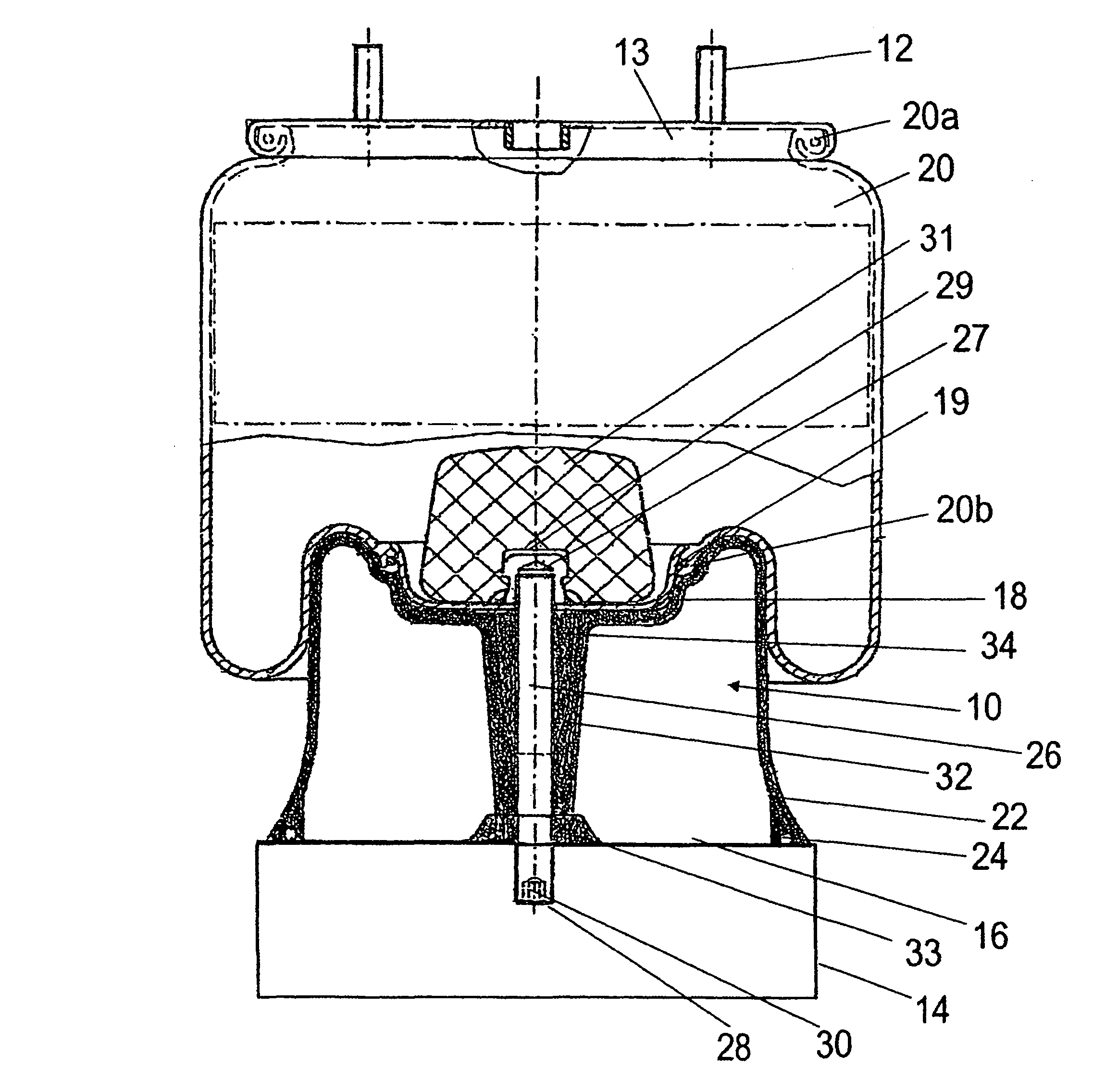
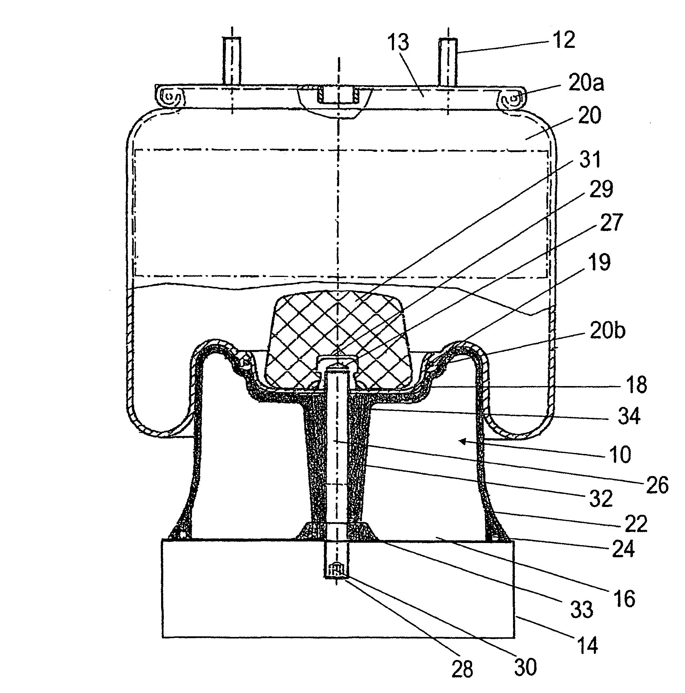
[0021]The represented pneumatic spring is arranged between a vehicle frame 12, not shown in greater detail, and an axle support 14, not represented in greater detail, of a utility vehicle. The pneumatic spring has a pneumatic spring bellows 20, which can be charged with compressed air and is connected at its upper edge 20a with a vehicle frame 12. For this purpose, the upper edge of the pneumatic spring bellows 20 is sealingly attached to a spring plate 13, which in turn is screwed to the vehicle frame 12.

[0022]At its lower edge, the pneumatic spring bellows 20 is sealingly clamped between the plunger piston bottom 18 at the top of the plunger piston 10 and a fastening plate 19. During spring movements, the pneumatic spring bellows 20 rolls off the exterior of the plunger piston shell 22. A support bolt 26 is arranged in the interior of the plunger piston 10, which is connected at its upper end 27 with the fastening plate 19 by a screw 29, and at its lower end 28 with the axle suppo...


PUM


Abstract

A plunger piston for an air spring. The air spring being active between a component which is to be cushioned by springs, in particular the vehicle frame, and a sprung component, in particular the axle carrier of a motor vehicle. The plunger piston is configured as a hollow piston which is connected to the sprung component at the lower plunger-piston end and to a pneumatic-spring bellows which can be loaded with compressed air at an upper plunger-piston head. The pneumatic-spring bellows is connected on the other side to the component which is cushioned by springs, and rolls on the outside of the plunger-piston skirt during suspension movements. The lower plunger-piston end has an open configuration and has a reinforcing element which encircles the edge region of the opening.

Description

BACKGROUND OF THE INVENTION[0001]1. Field of the Invention[0002]This invention relates to a plunger piston for a pneumatic spring, such as used with motor vehicles. A pneumatic spring acts between a component to be sprung, in particular the vehicle frame, and a resilient component, in particular the axle support of a motor vehicle. The plunger piston is a hollow body, with a plunger piston end located at a bottom and connected with the resilient component, and at a plunger piston end located at a top is connected with a pneumatic spring bellows, which can be charged with compressed air. The pneumatic spring bellows is connected with the resilient component and rolls off on an exterior of the plunger piston shell during spring movements.[0003]2. Discussion of Related Art[0004]Known pneumatic springs are employed in utility vehicles in particular, but also in machinery in which it is necessary to provide a spring action between two components which move in relation to each other. A sp...

Claims


Application Information

Patent Timeline
Patent Type & Authority Patents(United States)
IPC IPC(8): F16F9/04
CPCF16F9/057
Inventor EISE, MARTINASSMANN, JORG
Owner LKH KUNSTWERK
Why Eureka
Try Eureka