Imaging device using a first motion vector in an image that is obtained via an imaging system that can perform zooming and a second motion vector caused by performing zooming of the image

a technology of imaging system and motion vector, which is applied in the direction of television system, instrument, color signal processing circuit, etc., can solve the problems of inability to reduce the blurring of an image on the basis of the detection result, the detection of motion vector caused by the shaking of the device while zooming is performed, and the inability to extract only the motion vector caused by the shaking of the device from the detected motion vector, etc., to achieve the effect of suppressing the blurring of an imag

Active Publication Date: 2012-02-28
CANON KK
View PDF18 Cites 8 Cited by
  • Summary
  • Abstract
  • Description
  • Claims
  • Application Information

AI Technical Summary

Benefits of technology

[0010]At least one exemplary embodiment is directed to a method for suppressing blurring of an image while zooming is performed on the basis of motion vectors that are detected while zooming is performed.
[0013]A device in accordance with at least one exemplary embodiment can reduce the blurring of an image or detect a moving subject, while zooming is performed.

Problems solved by technology

Unfortunately, for example, when the viewing angle is changed by optical zooming or an image is magnified or reduced by electronic zooming, the motion vector caused by the zooming operation may be erroneously detected as a motion vector caused by shaking of the device.
However, even in the method discussed in Japanese Patent Laid-Open No. 7-203280, detection of motion vectors caused by shaking of the device while zooming is performed and reduction of the blurring of an image on the basis of the result of the detection cannot be performed.
That is to say, when shaking of the device occurs while zooming is performed, it is difficult to extract only the motion vectors caused by the shaking of the device from the detected motion vectors.
In this situation, when motion vectors caused by zooming extend beyond a detection area for detecting motion vectors, the motion vectors cannot be detected.

Method used


Image

  • Imaging device using a first motion vector in an image that is obtained via an imaging system that can perform zooming and a second motion vector caused by performing zooming of the image
  • Imaging device using a first motion vector in an image that is obtained via an imaging system that can perform zooming and a second motion vector caused by performing zooming of the image
  • Imaging device using a first motion vector in an image that is obtained via an imaging system that can perform zooming and a second motion vector caused by performing zooming of the image

Examples


first exemplary embodiment

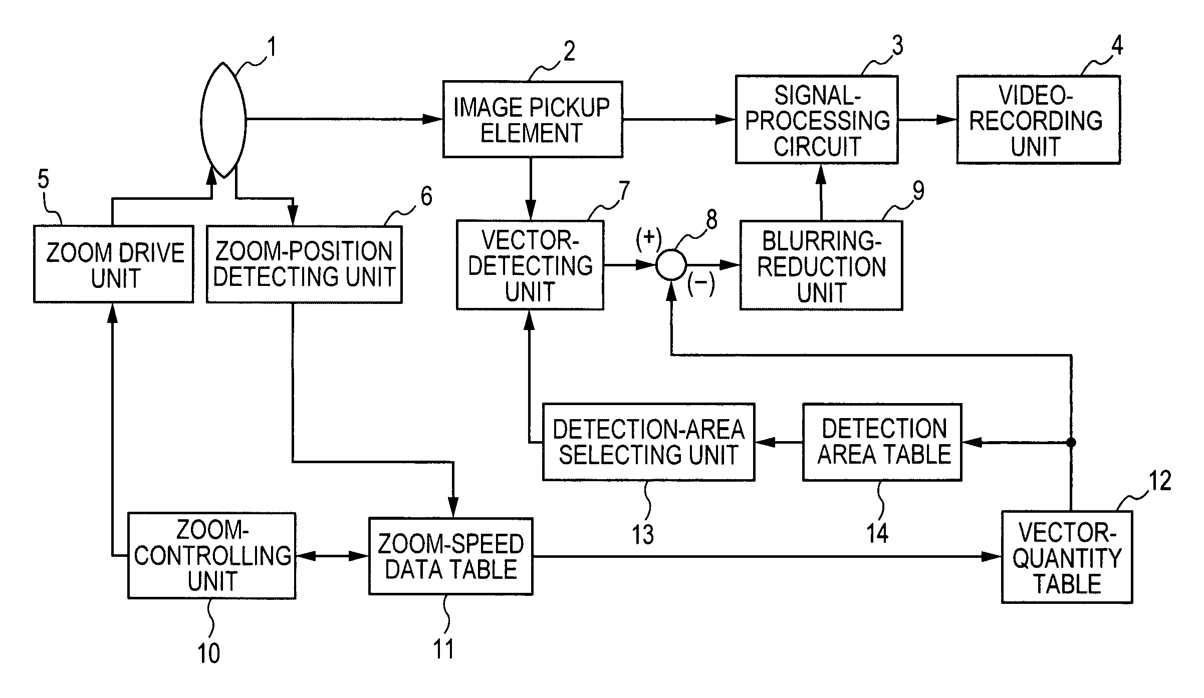
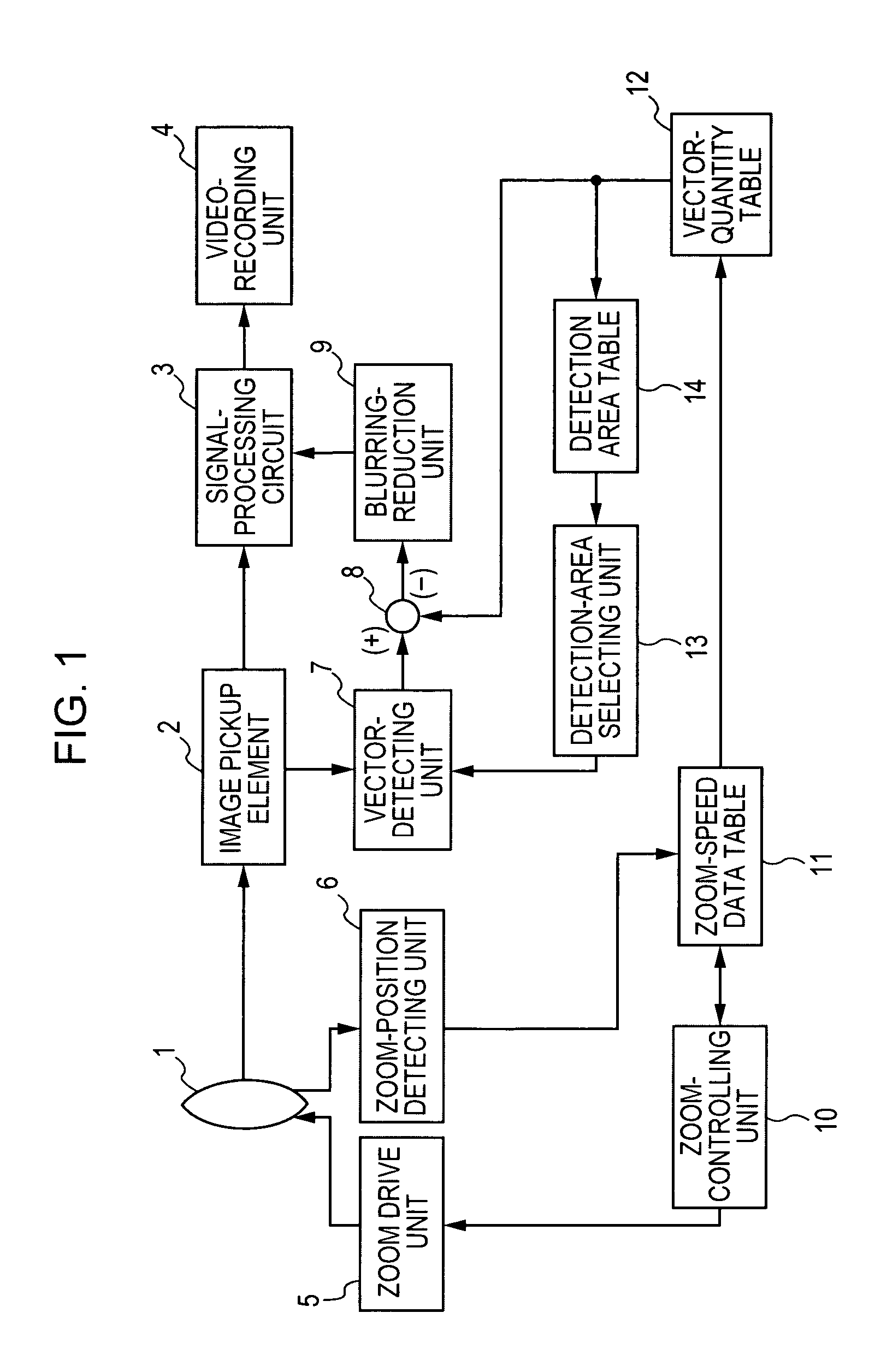
[0034]FIG. 1 is a system block diagram showing the structure of an imaging device (e.g., video cameras, digital cameras, optical instruments, other imaging devices as known by one of ordinary skill in the relevant arts and equivalents) having a moving-image shooting function, according to a first exemplary embodiment.

[0035]As shown in FIG. 1, the imaging device includes an optical imaging system 1 that includes an optical element (e.g., a zoom lens) and an image pickup element (photoelectric transducer) 2 that performs photoelectric conversion on an image of a subject formed by the optical imaging system 1 (e.g., a charge-coupled device (CCD) sensor or a complementary metal-oxide semiconductor (CMOS) sensor, other photoelectric conversion elements as known by one of ordinary skill in et relevant art and equivalent).

[0036]The imaging device further includes a vector-detecting unit 7 that detects motion vectors in an image obtained by the image pickup element 2, a zoom drive unit 5 th...

second exemplary embodiment

[0061]In an imaging device that includes an optical imaging system that can change the viewing angle by driving a zoom lens and has an automatic focusing function, which controls the driving of a focus lens included in the optical imaging system, focus may not be maintained. Such a situation occurs when the focus lens cannot be controlled in a case where the zoom lens is driven at a high speed because an automatic focusing operation cannot follow a high-speed zooming operation. This is because focus control is performed by the contrast detection method (the TV-AF method) in an imaging device, such as a video camera. In the contrast detection method, a focal point at which the highest frequency component is achieved is searched for by driving the focus lens with reference to high frequency components in an image.

[0062]In the situation described above, even when the movement of the zoom lens is controlled as illustration in the first exemplary embodiment, motion vectors cannot be dete...

third exemplary embodiment

[0079]In the first and second exemplary embodiments, reduction of the blurring of an image using motion vectors in the middle of a zooming operation is described. It can be determined whether a subject is a moving subject using the methods according to exemplary embodiments which can detect motion vectors in the middle of a zooming operation. In the first and second exemplary embodiments, the motion vector (the third motion vector) caused by shaking of the imaging device is extracted. When the third motion vector is extracted in the same way as in the first and second exemplary embodiments in a case where there is no shaking of the imaging device, the third motion vector is then caused by the movement of a subject.

[0080]When the third motion vector extracted in this way is used, it is determined whether a subject is a moving subject, and then an operation that follows the moving subject, for example, automatic focusing control, can be performed.


PUM


Abstract

At least one exemplary embodiment is directed to an imaging device which includes a detecting unit that detects a first motion vector in an image that is obtained via an imaging system that can perform zooming, and a storage unit that stores in advance a second motion vector caused by performing zooming of the image.

Description

BACKGROUND OF THE INVENTION[0001]1. Field of the Invention[0002]The present invention relates to methods for image processing using motion vectors in imaging devices.[0003]2. Description of the Related Art[0004]Conventional methods have been proposed, in which motion vectors between frames or fields of moving images that are captured are detected for reducing the blurring of images, where the blurring can be caused by, for example, by hand-shake that occurs at the time of shooting the images. The conventional systems also determine whether a subject is a moving subject, and can also perform image compression.[0005]Blurring of an image is reduced by, for example, shifting an image area to be output of the image obtained from an image pickup element or moving a part of an optical system in the direction perpendicular to the optical axis, on the basis of the result of detecting the motion vectors.[0006]Unfortunately, for example, when the viewing angle is changed by optical zooming or ...

Claims


Application Information

Patent Timeline
Patent Type & Authority Patents(United States)
IPC IPC(8): H04N5/262
CPCH04N5/232H04N5/23212H04N5/23248H04N5/23254H04N5/23258H04N5/23274H04N5/23296H04N23/6842H04N23/6811H04N23/68H04N23/6812H04N23/69
Inventor ISHIKAWA, DAISUKE
Owner CANON KK
Why Eureka
Try Eureka