
Die cushion device of pressing machine

a technology of press machine and die cushion, which is applied in the direction of presses, forging presses, manufacturing tools, etc., can solve the problems of low response speed of servo valve, poor follow-up capability of pressure to pressure command, and insufficient restriction of surge pressure, so as to prevent the generation of surge pressure and facilitate follow-up.

Active Publication Date: 2012-03-06
AIDA ENG LTD
View PDF12 Cites 11 Cited by
  • Summary
  • Abstract
  • Description
  • Claims
  • Application Information

AI Technical Summary

Benefits of technology

The solution effectively restricts surge pressure, ensures excellent follow-up capability for die-cushion pressure commands, and achieves cost-effective control of die-cushion pressure and knock-out position using a single proportional flow-rate control valve.

Problems solved by technology

However, in the cushion pressure controller of the die-cushion device described in JP '295, the opening degree of the servo valve is added in an auxiliary manner according to the press driving speed, but since the discharge flow rate from the hydraulic cylinder is controlled by pressure feedback, if the slide speed is high, a response speed of the servo valve becomes low with respect to the rising response speed of the pressure, which leads to problems that surge pressure can not be restricted sufficiently and if a change is caused in the press driving speed or pressure command, follow-up capability of the pressure to the pressure command becomes poor.
Also, since the servo valve is used only as pressure control device for controlling the die-cushion pressure and a pneumatic circuit is provided for operating another cylinder at knock-out action, a plurality of expensive servo valves should be used, which is a problem.
On the other hand, in JP '600, for the purpose of restriction of surge pressure generated when the slide collides against the cushion pad at a high speed, the cushion pad is preliminarily accelerated downward in order to decrease the relative speed of the slide and the cushion pad, but this causes a problem of restriction on molding.
And this causes a problem that expensive servo valves should be used in plural as described in JP '295.

Method used


Image

  • Die cushion device of pressing machine
  • Die cushion device of pressing machine
  • Die cushion device of pressing machine

Examples


Embodiment Construction

[0036]One embodiment of a die-cushion device of a press machine according to the present invention will be described in details according to the attached drawings.

[Configuration of a Die-Cushion Device]

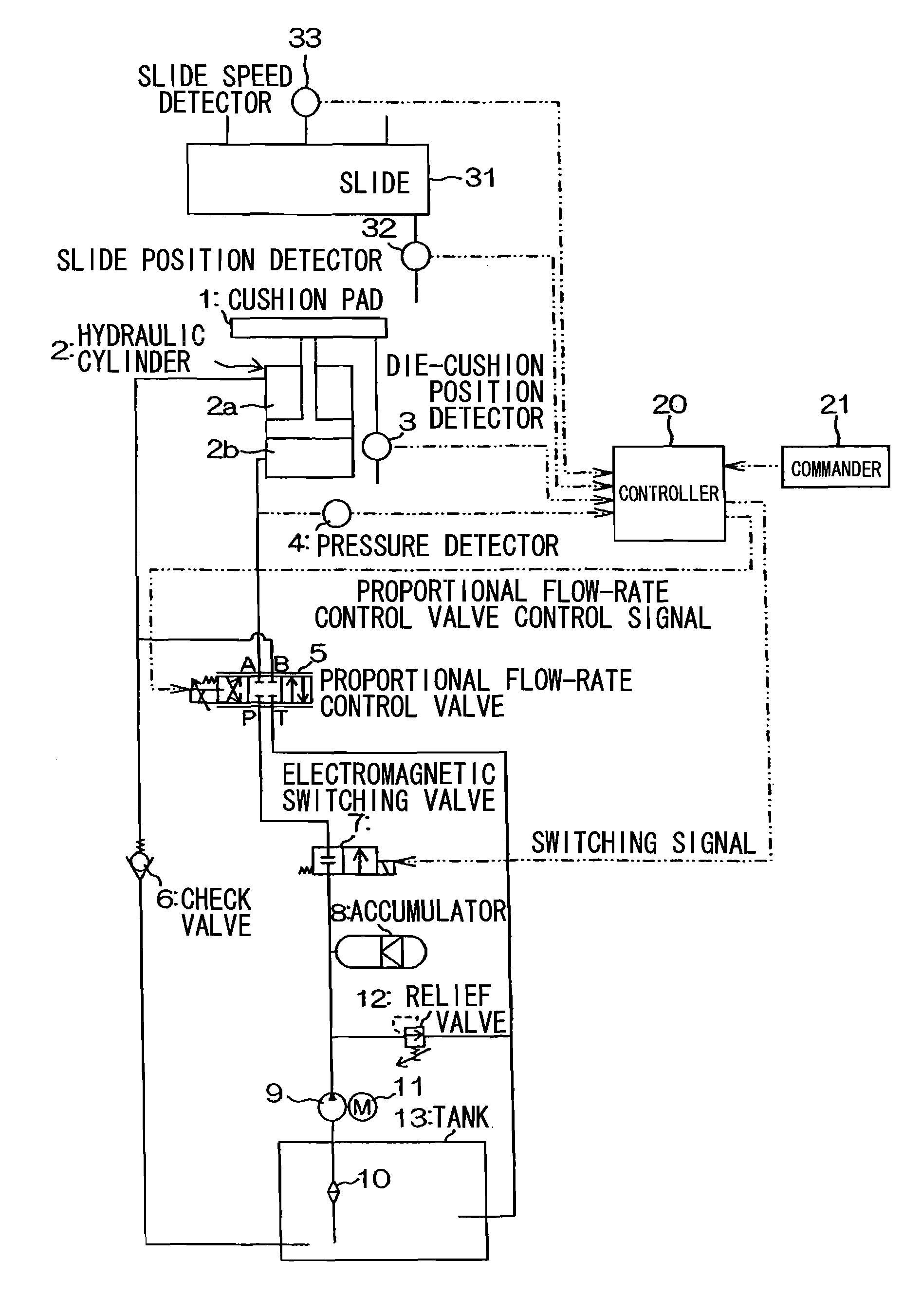
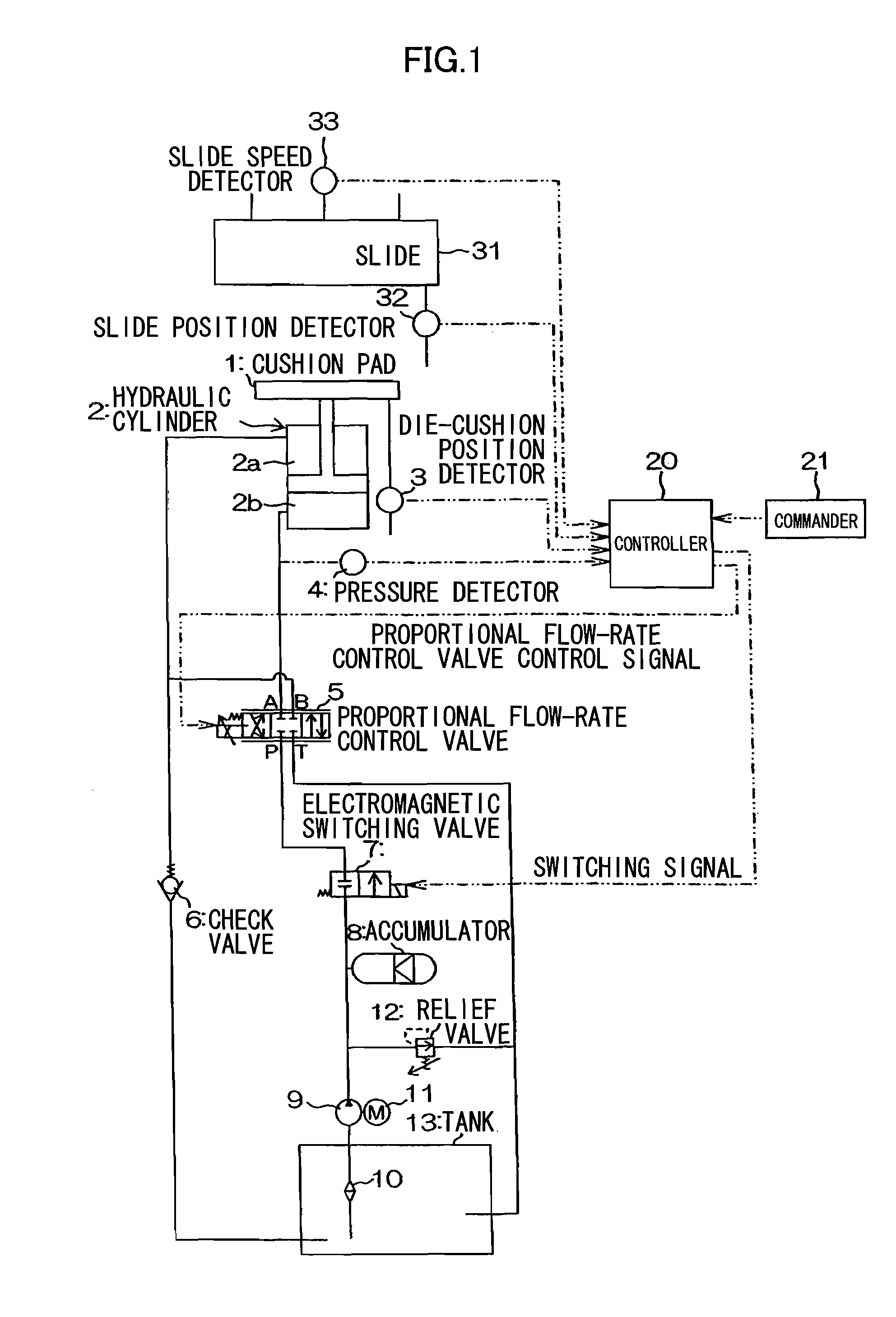
[0037]FIG. 1 is a diagram illustrating an embodiment of the die-cushion device of a press machine according to the present invention. In the FIG. 1, a cushion pad 1 is supported by a single or a plurality of hydraulic cylinders 2. At the cushion pad 1, a die-cushion position detector 3 (or proximity switch) is provided.

[0038]To a flow passage connected to a lower chamber 2b side of the hydraulic cylinder 2, a pressure detector 4 for detecting the pressure of the lower chamber 2b is connected and an A port of a 4-port 2-position proportional flow-rate control valve (hereinafter, referred to simply as “proportional flow-rate control valve”) 5 is connected, while to a flow passage connected to an upper chamber 2a side of the hydraulic cylinder 2, a B port of the proportional flow-rate co...


PUM

PropertyMeasurementUnit
pressureaaaaaaaaaa
slide speedaaaaaaaaaa
speed detectingaaaaaaaaaa

Abstract

In a die-cushion device of a press machine a controller controls an opening degree of a proportional flow-rate control valve to an appropriate opening degree in order to control the flow rate flowing out of a lower chamber of a hydraulic cylinder supporting a cushion pad before a slide collides against the cushion pad using a die-cushion pressure command commanded from a commander in advance and a slide speed signal inputted from a slide speed detector. By this, generation of a surge pressure when a slide collides against the cushion pad at a high speed is restricted.

Description

CROSS REFERENCE TO PRIOR APPLICATION[0001]This is a U.S. national phase application under 35 U.S.C. §371 of International Patent Application No. PCT / JP2005 / 020829 filed Nov. 14, 2005, and claims the benefit of Japanese Application No. 2004-332157 filed Nov. 16, 2004, both of them are incorporated by reference herein. The International Application was published in Japanese on May 26, 2006 as International Publication No. WO / 2006 / 054512 under PCT Article 21(2).FIELD OF THE INVENTION[0002]The present invention relates to a die-cushion device of a press machine, and particularly to a die-cushion device which enables control of cushion action and cushion capability of a press machine such as a mechanical press, electric (servo) press and hydraulic press.BACKGROUND[0003]A cushion-pressure controller which can restrict surge pressure at the start of press molding and pressure override at a switching of press driving speed has been proposed in Japanese Laid-Open Patent Application No. 5-131...

Claims


Application Information

Patent Timeline
Patent Type & Authority Patents(United States)
IPC IPC(8): B21J9/18
CPCB21D24/02B30B15/0052B30B15/02B30B15/061B30B15/16
Inventor KOHNO, YASUYUKIHASEBA, KATSUNORIHASEBA, JUNKO
Owner AIDA ENG LTD
Learn More