Vane-type cam phaser having dual rotor bias springs

a cam phaser and bias spring technology, applied in the direction of yielding couplings, valve arrangements, couplings, etc., can solve the problems of unacceptably high rate of locking failure, rotor being slightly cocked within, and inability to reliably lock, so as to prevent any spring distortion and increase the reliability of locking

Active Publication Date: 2012-03-06
DELPHI TECH IP LTD
View PDF2 Cites 7 Cited by
  • Summary
  • Abstract
  • Description
  • Claims
  • Application Information

AI Technical Summary

Benefits of technology

[0011]A first pre-loaded bias spring disposed on the phaser cover plate urges the rotor toward the locking position from any rotational position retarded of the locking position. When the rotor is moving in a phase-advance direction, at or near the rotor locking position the bias spring system becomes disengaged from the rotor. When the rotor is moving in a phase-retard direction, at or near the rotor locking position the bias spring system is engaged, causing the rotor to decelerate and thereby increasing the reliability of locking.
[0012]A first improvement over the prior art is a cylindrical spring guide extending axially from the phaser cover plate to prevent any spring distortion from reaching the rotor and thereby undesirably cocking the rotor within the stator.
[0013]A second improvement over the prior art is a second bias spring engaged with the rotor and the stator to bias the rotor in a phase-advance direction over the full range of phaser authority to compensate for additional phase-retarding torque loads imposed on the camshaft by additional non-valve actuation functions such as mechanically pumping fuel.

Problems solved by technology

A known problem in such phasers is that there is no mechanical means such as a stop to assist in positioning the rotor for locking in an intermediate position; thus, locking is not reliable, and an unacceptably high rate of locking failures may occur.
A problem not addressed is that the torsion bias spring may generate an unwanted torque on the rotor about an axis orthogonal to the rotor axis, causing the rotor to become slightly cocked within the stator chamber before the phaser is installed onto the end of a camshaft during engine assembly.
An additional problem more recently recognized is the fact that in many modern engines the camshaft is called upon to perform cyclic functions in addition to the opening and closing of combustion valves.
The additional torque load in the phase-retard direction can impede the function of the bias spring and also slow the response of the rotor in the advance direction beyond the rotary locking position at which point the bias spring no longer engages the rotor.

Method used


Image

  • Vane-type cam phaser having dual rotor bias springs
  • Vane-type cam phaser having dual rotor bias springs
  • Vane-type cam phaser having dual rotor bias springs

Examples


Embodiment Construction

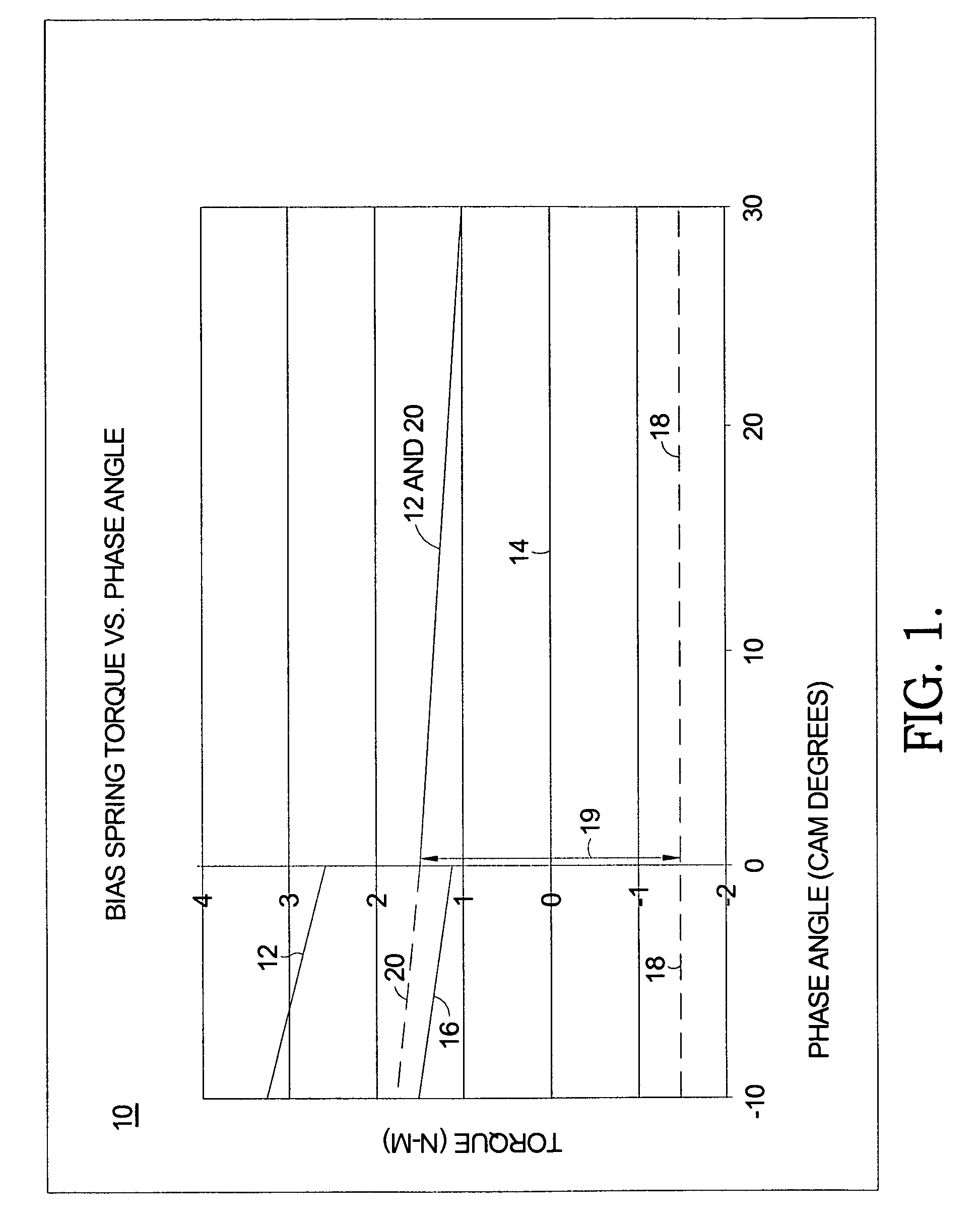
[0020]Referring to FIG. 1, graph 10 shows the interrelationships of various torque and bias spring functions in a camshaft phaser in accordance with the present invention. A rotational locking position of a rotor to a stator is defined as 0° phase angle. To permit reliable locking, the net torque on the rotor must be in the vicinity of zero Newton-meters. During engine cold start, the bias spring system comprising two bias springs as described below exerts a net torque in the phase-advance direction that exceeds the torque of the camshaft in the phase-retard direction, causing the rotor to be advanced from a fully retarded starting position (−100) to the locking position (0°). This is shown in Curve 12. Thereafter, at all rotor phase angles advanced from 0°, it is desired that the bias spring system exert little or no net torque, as shown in Curve 14. In the prior art, this is accomplished with a single bias spring (the innermost of two springs in the present invention as described ...


PUM


Abstract

A vane-type camshaft phaser for varying the timing of combustion valves including a first torsional bias spring disposed on a cover plate spring guide and grounded to the cover plate and to a slot in a spring retainer to urge the rotor toward an intermediate locking position from any position retarded of the locking position. A second torsional bias spring also anchored to the cover plate and spring retainer urges the rotor in the advance direction over the full range of phaser authority to compensate for added camshaft torque loads imposed by non-valve actuating functions such as driving a mechanical fuel pump.

Description

RELATIONSHIP TO OTHER APPLICATIONS AND PATENTS[0001]This application claims the benefit of U.S. Provisional Patent Application Ser. No. 61 / 070,365, filed Mar. 21, 2008, which is hereby incorporated by reference in its entirety.TECHNICAL FIELD[0002]The present invention relates to vane-type camshaft phasers for varying the phase relationship between crankshafts and camshafts in internal combustion engines; more particularly, to such phasers wherein a locking pin assembly is utilized in a phaser having a first bias spring to assist in locking a phaser rotor at a rotational position intermediate between full phaser advance and full phaser retard positions; and most particularly, to such a phaser having a second bias spring for compensating for additional camshaft torque loads imposed by additional camshaft tasks.BACKGROUND OF THE INVENTION[0003]Camshaft phasers for varying the phase relationship between the crankshaft and a camshaft of an internal combustion engine are well known. A pr...

Claims


Application Information

Patent Timeline
Patent Type & Authority Patents(United States)
IPC IPC(8): F01L1/34
CPCF01L1/3442F01L2001/34483
Inventor FISCHER, THOMAS H.GAUTHIER, DANIEL G.
Owner DELPHI TECH IP LTD
Why Eureka
Try Eureka