
Cantilever brake device

a brake device and cantilever technology, applied in the direction of bicycle brakes, braking systems, cycle equipments, etc., can solve problems such as destabilization of brakes, and achieve the effects of reducing squeaking noise, increasing braking power and tension, and easy adjustment of brake shoes

Inactive Publication Date: 2012-03-06
BIKEBIZ III
View PDF5 Cites 3 Cited by
  • Summary
  • Abstract
  • Description
  • Claims
  • Application Information

AI Technical Summary

Benefits of technology

"The present invention is a cantilever brake device for bicycles that solves problems of traditional brakes by providing a durable design with improved features such as ease of adjustment, reduction of squeaking noise, increase of braking power, and tension. The adjustable arm members, cable tension and traction at the bottom of the device, easy adjustability of brake shoes, and rigid shoe housing members offer numerous advantages over traditional brakes. The angle adjustment of the arm members, cable tension and traction point at the distal end, and easy adjustability of brake shoes avoid excessive deflection of brake pads. The bottom trunk portions of the brakes apply brakes more evenly and uniformly against the rim surface for greater braking power and mechanical advantage. The brake shoes are adjustable on both the y-axis for height adjustment and the x-axis for roll angle and pitch angle adjustments. The foregoing and other objectives, features, and advantages of the invention will be more readily understood upon consideration of the following detailed description of the invention."

Problems solved by technology

The brake shoes being placed farther away from the shoe housing member destabilizes the brakes due to excessive deflection of the brake pads.

Method used


Image

  • Cantilever brake device
  • Cantilever brake device
  • Cantilever brake device

Examples


Embodiment Construction

[0025]As commonly mentioned in the description to describe the movement of the various components in different directions, a movement in a y-axis pertains to the vertical direction from top to bottom or bottom to top. Movement in an x-axis pertains to the horizontal direction from left to right or right to left. Movement in a z-axis pertains to the horizontal direction from front to back or back to front. Furthermore, the roll angle pertains to angle adjustment on a vertical axis, and the pitch angle pertains to angle adjustment on a horizontal axis.

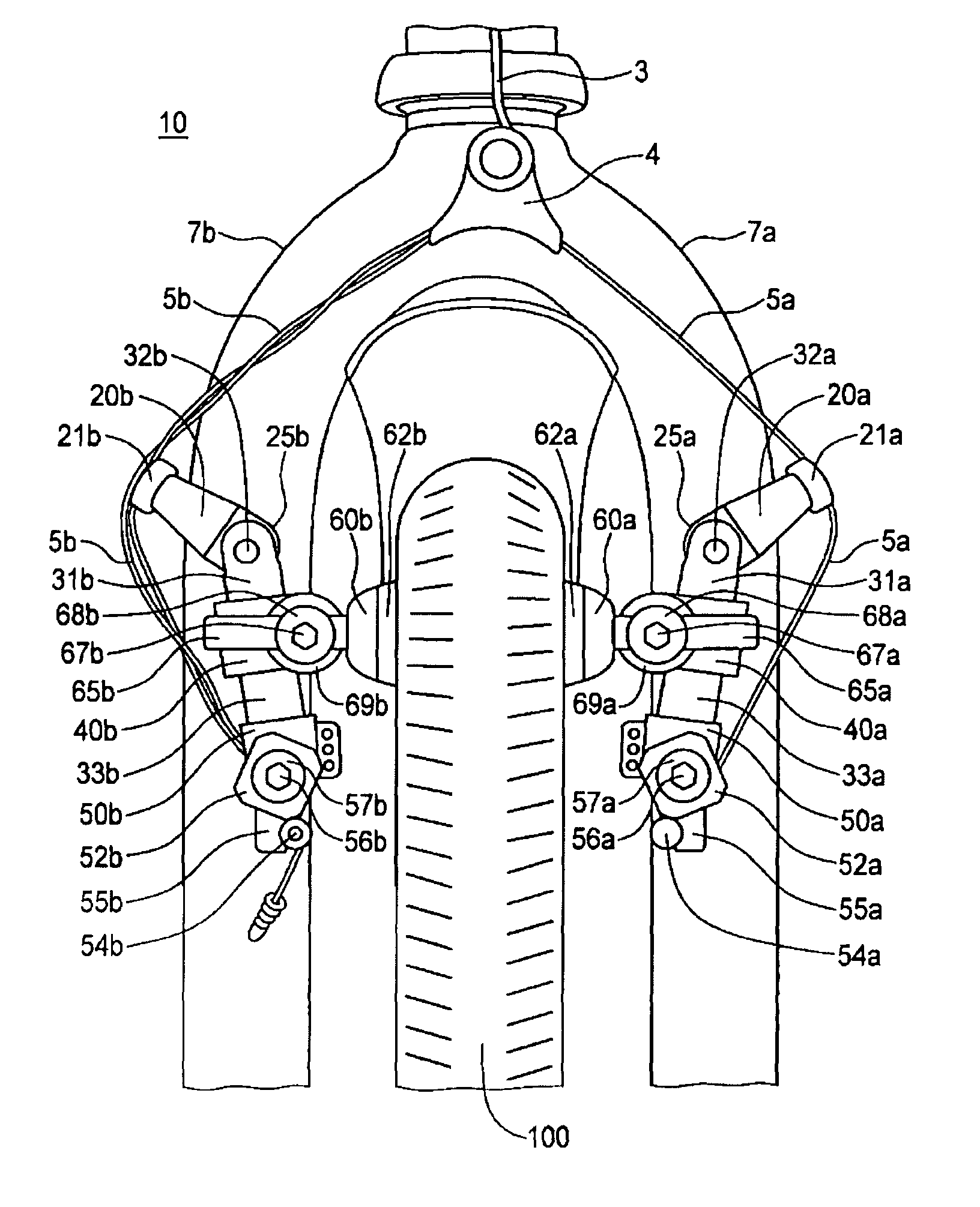
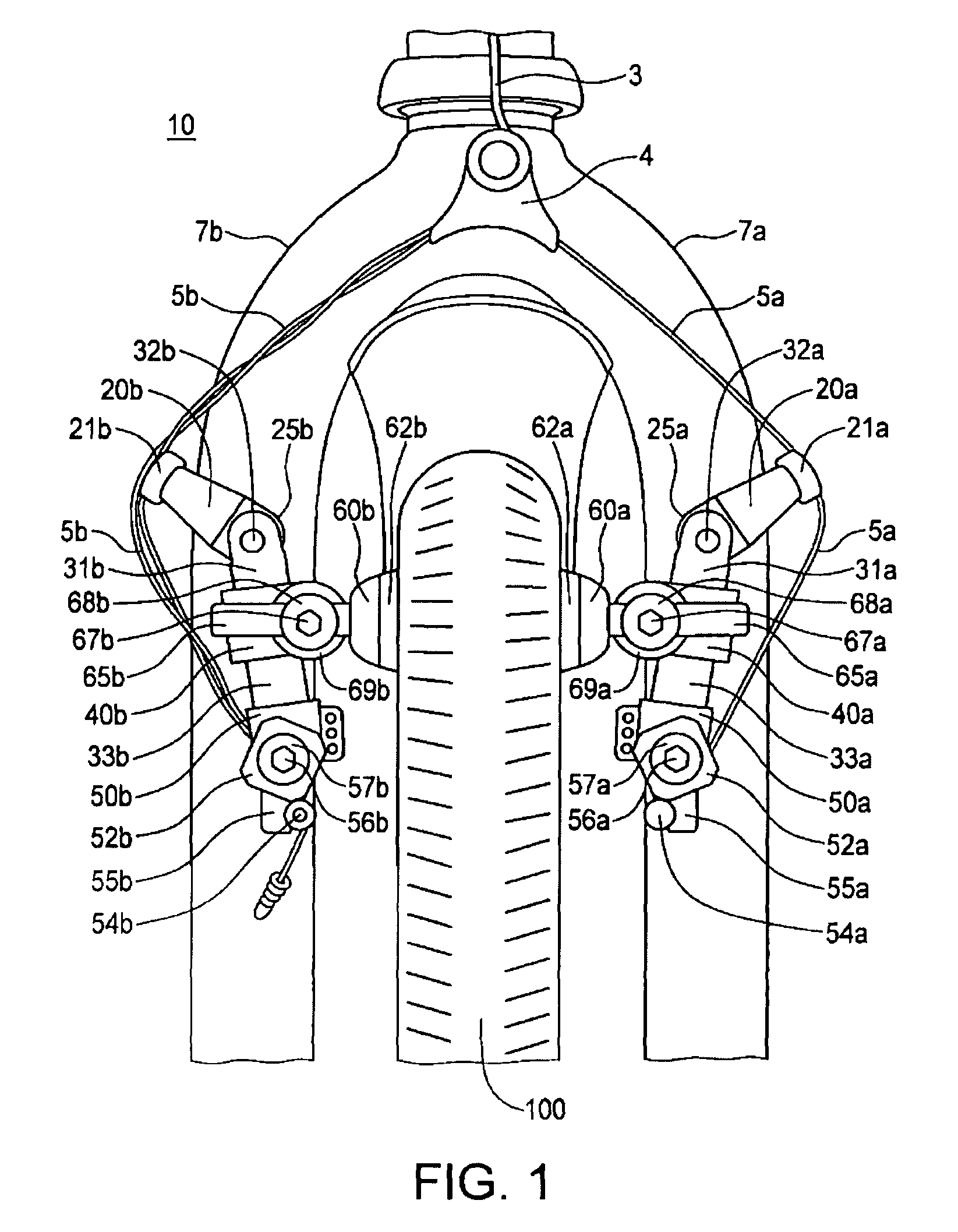
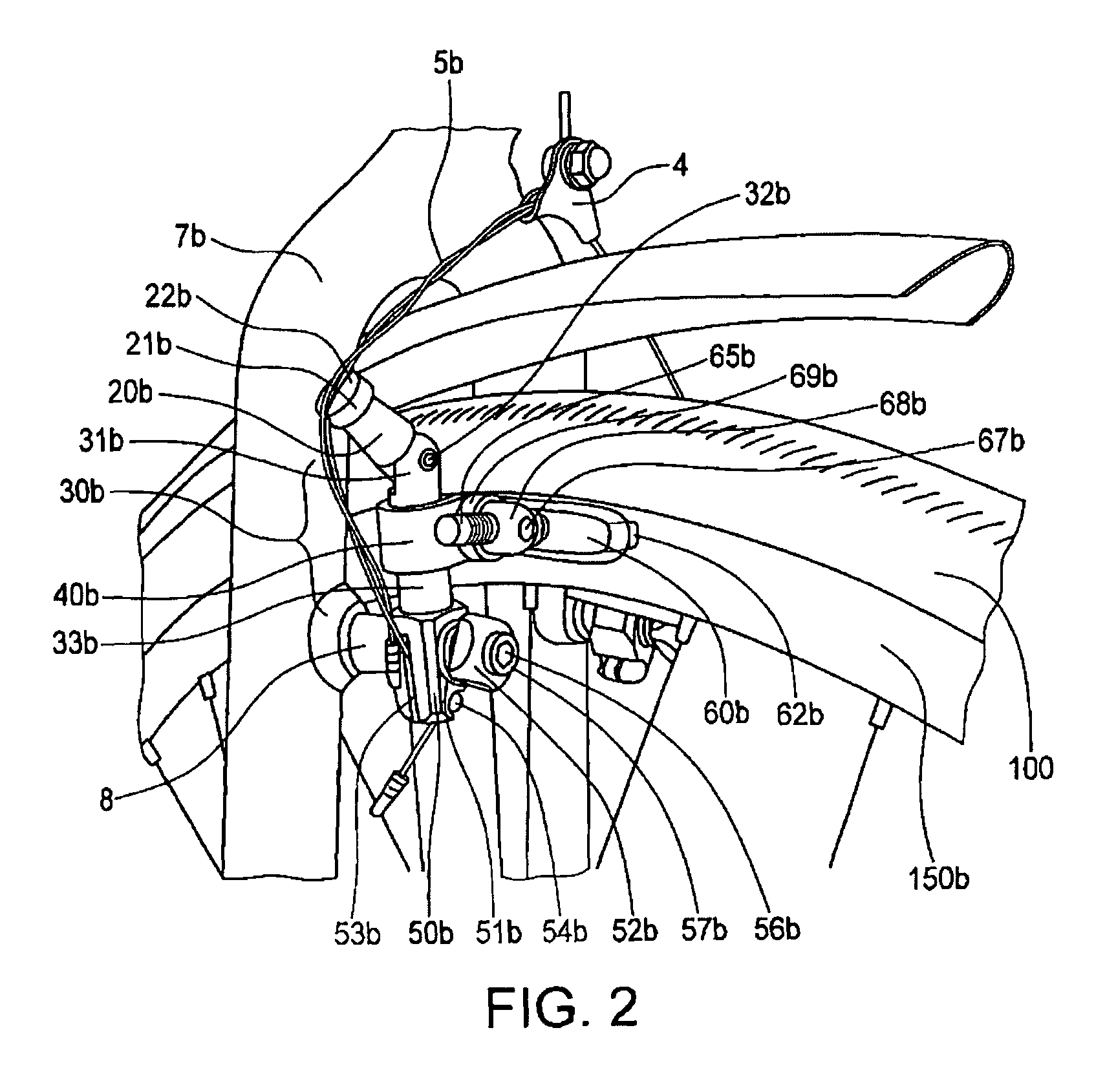
[0026]A cantilever brake device 10 comprises a pair of opposing brake arm assemblies with a pair of adjustable arm members 20a, 20b, a pair of body members 30a, 30b, a pair of shoe housing members 40a, 40b, a pair of brake supports 65a, 65b, a pair of brake shoes 60a, 60b, a pair of brake pads 62a, 62b, a pair of trunk portions 50a, 50b, a pair of coil springs 51a, 51b, and a pair of spring adjusters 52a, 52b. The specification herein ma...


PUM


Abstract

A cantilever brake device is disclosed having a pair of opposing brake arm assemblies with cable tension or the traction point at the distal end of the body members at the bottom trunk portions rather than at the upper level by the adjustable arm members. By moving the cable tension and traction point to the bottom level of the body members, the brakes are applied more evenly and uniformly against and onto the rim surface for greater braking power and mechanical advantage. The cantilever brake device is also disclosed having a shoe housing member that is easily adjustable on a y-axis for height adjustment of the brake shoes since the brake shoes are each mounted on the shoe housing member and allows uniform adjustment of both shoe housing members holding the brake shoes. The shoe housing member is easily rotatable to modify the pitch angle of the brake shoes on a pivotal, horizontal axis to align the brake pads squarely against the rim surface so that the top and bottom portions of the brake pads touch the rim surface equally and uniformly when brakes are applied. Consequently, all of the vertical, horizontal, roll angle, pitch angle, and toe-in adjustments are easily achievable for fine tuning the brakes by using the present cantilever brake device.

Description

CROSS-REFERENCE TO RELATED APPLICATION[0001]The present application is an application claiming the benefit under 35 USC Section 119(e) of U.S. Provisional Patent Application Ser. No. 61 / 037,307, filed Mar. 17, 2008. The present application is based on and claims priority from the provisional application, the disclosure of which is hereby expressly incorporated herein by reference in its entirety.BACKGROUND OF THE INVENTION[0002]The present invention relates generally to a brake device for a bicycle. More specifically, the present invention is directed to a cantilever brake device.[0003]Different brake devices are adapted into different bicycles whether used for off-roading, touring, or a combination of both, to provide a stable and reliable braking device to accommodate the user's needs. Larger bicycles such as tandem, travel, or loaded touring bicycles, typically require stronger braking devices due to the added weight of a passenger, touring necessities, or a combination of both. ...

Claims


Application Information

Patent Timeline
Patent Type & Authority Patents(United States)
IPC IPC(8): B62L3/00
CPCB60T1/06B60T11/046F16D55/2245
Inventor TOWLE, DANIEL
Owner BIKEBIZ III
Learn More