
Power charging assembly and method that includes a low voltage electrical device operable with pulse width modulation (PWM) control

a technology of power charging and low voltage electrical devices, applied in the direction of battery/fuel cell control arrangement, electric devices, electrochemical generators, etc., can solve the problems of reducing the service life of the contactor, unsatisfactory damage,

Active Publication Date: 2012-03-06
APTIV TECH LTD
View PDF4 Cites 35 Cited by
  • Summary
  • Abstract
  • Description
  • Claims
  • Application Information

AI Technical Summary

Benefits of technology

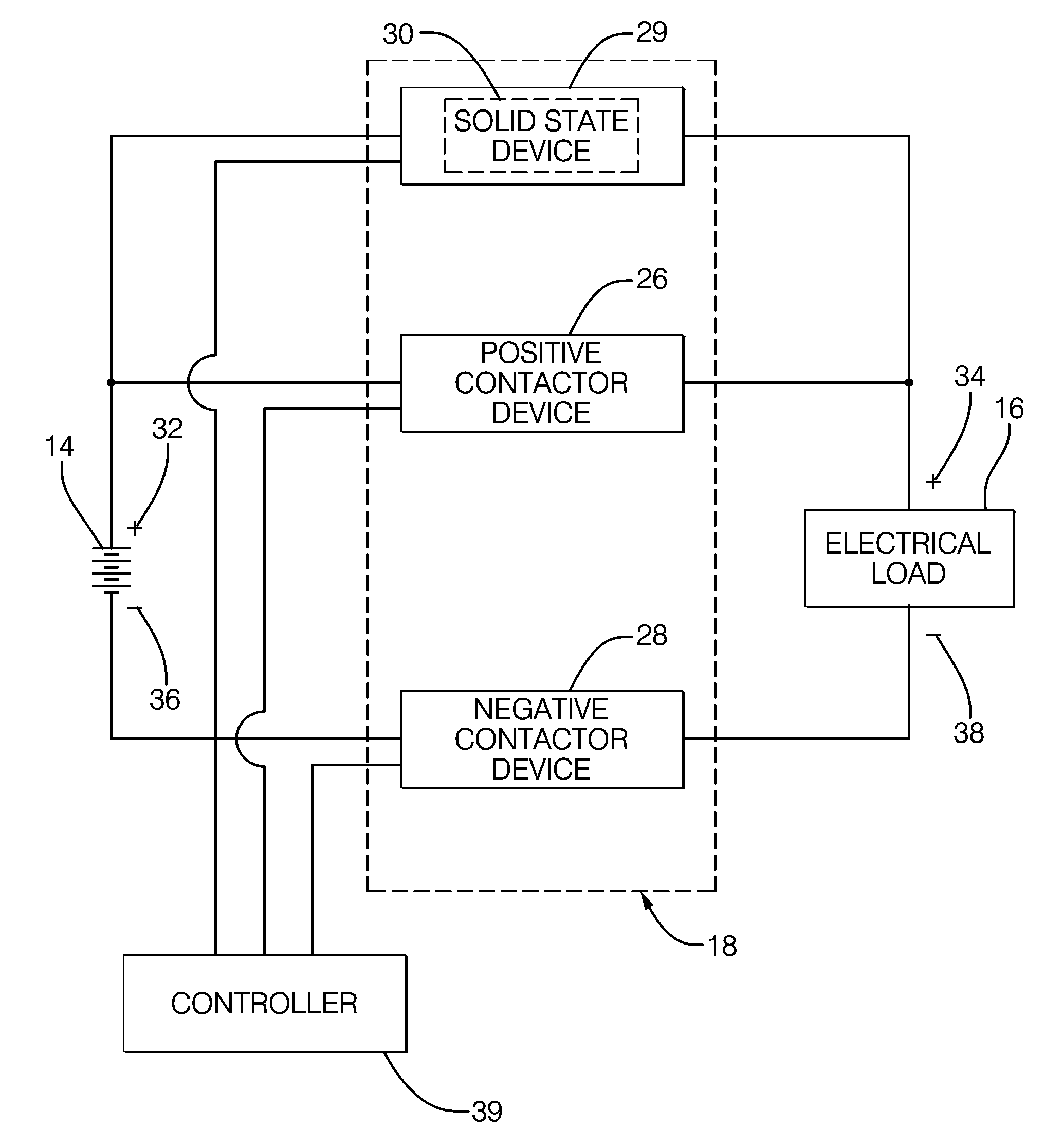
The power charging assembly described in this patent is used to charge and discharge the electrical load of a hybrid electric vehicle or electric vehicle. It includes a positive contactor device, a negative contactor device, and a non-contactor device that work together to provide a pre-charge state, a steady-state high-current charging state, and an unconnect state for the electrical load. The technical effects of this assembly include improved charging efficiency and reliability, as well as improved safety and control during charging and discharging operations.

Problems solved by technology

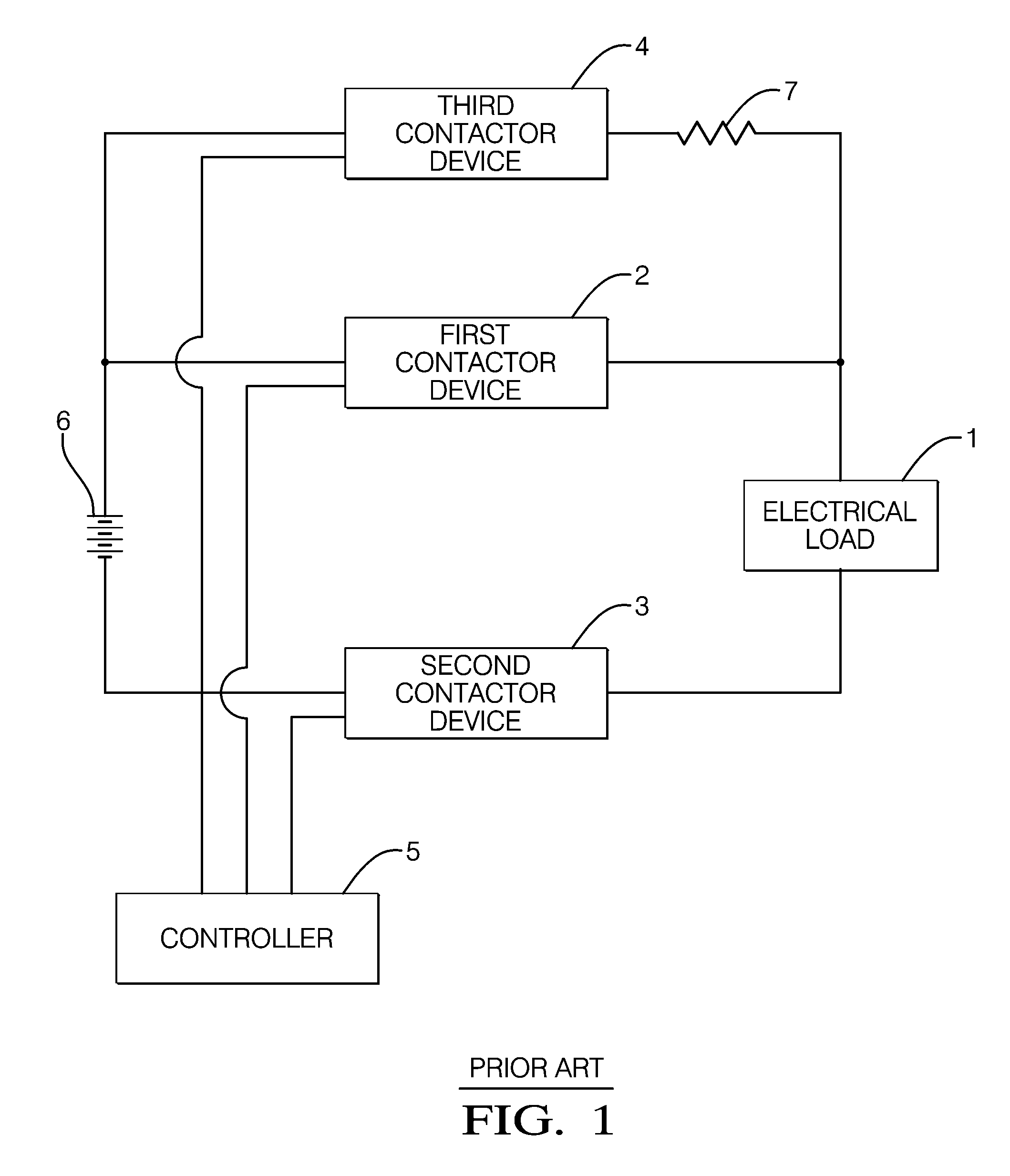
Closing the first and second contactor device into an electrical load having a large electrical potential may cause undesired damage or reduced service life to the contactor.
Similarly, interruption or breaking of the electrical circuit by the contactor under large, or heavy electrical load may also result in the undesired consequence of reduced service life of the contactor.
The third contactor relay (4) that supplies the voltage of the battery (6) to the electrical load (1) has an undesired large size, weight, and cost.
The current-limiting resistor (7) has an undesired large size and weight and also radiates undesired heat in relation to the voltage applied thereacross.

Method used


Image

  • Power charging assembly and method that includes a low voltage electrical device operable with pulse width modulation (PWM) control
  • Power charging assembly and method that includes a low voltage electrical device operable with pulse width modulation (PWM) control
  • Power charging assembly and method that includes a low voltage electrical device operable with pulse width modulation (PWM) control

Examples


Embodiment Construction

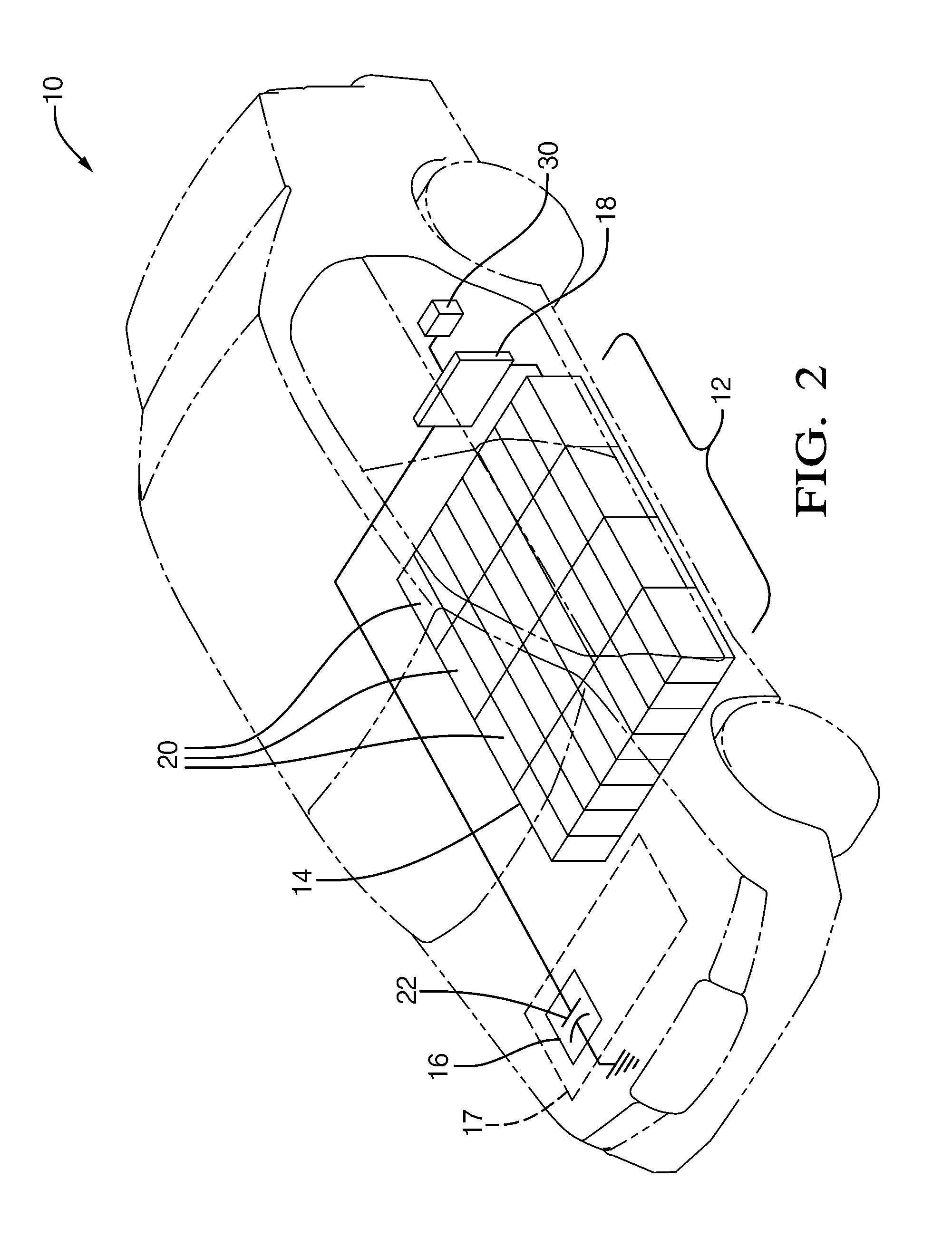
[0017]A hybrid electric vehicle (HEV) combines a conventional internal combustion engine propulsion system with an electric propulsion system. An electric vehicle (EV) may generally have an electrical propulsion system only. The electric propulsion system assists the HEV or EV to achieve increased fuel economy over a vehicle having only a conventional internal combustion engine. Referring to FIG. 2, a common known HEV is a hybrid electric car 10. The invention is not limited for use in only hybrid electric car 10, but is suitable for any type of vehicle employing HEV technology. For example, hybrid electric trucks, such as pick-ups and tractor-trailer trucks are also growing in consumer popularity.

[0018]In accordance with a preferred embodiment of this invention, referring to FIG. 2, car 10 includes an electric propulsion system 12. Electric propulsion system 12 includes a battery 14, a single electrical load 16, and a power charging assembly 18 connected respectively therewith. Ass...


PUM

PropertyMeasurementUnit
contact voltageaaaaaaaaaa
voltage ratingaaaaaaaaaa

Abstract

A power charging assembly and methods are provided to provide a pre-charge low-current state, a steady-state, high-current charging state, and an unconnect state for an electrical load of an electrical propulsion system in a hybrid electrical vehicle (HEV). The power charging assembly includes a positive contactor device, a negative contactor device, and a non-contactor device means. The rate at which that electrical load is pre-charged may be effectively controlled by using a pulse-width modulated (PWM) signal received by the non-contactor device means. A current-only carrying positive or negative contactor may be configured with the non-contactor device means to further prevent electrical arcing of the contacts of the positive and the negative contactor during power charging assembly operation.

Description

TECHNICAL FIELD[0001]This invention relates to a power charging assembly in an electrical propulsion system for a hybrid electric vehicle (HEV) or an electric vehicle (EV), more particularly, the power charging assembly includes a positive contactor device, a negative contactor device, and a non-contactor device means that operatively cooperate to provide a pre-charge low-current state, a steady-state, high-current charging state, and an unconnect state for an electrical load.BACKGROUND OF INVENTION[0002]It is known, as shown in the prior art configuration of FIG. 1, to electrically charge and discharge an electrical load (1) used in a hybrid electric vehicle (HEV) or electric vehicle (EV) (not shown). The electrical load (1) is pre-charged to a predetermined voltage value before a steady-state high current is applied to the load (1). A first, or positive contactor device (2), a second, or negative contactor device (3), and a third contactor device (4) are operatively controlled wit...

Claims


Application Information

Patent Timeline
Patent Type & Authority Patents(United States)
IPC IPC(8): H01M10/46B60L50/16
CPCB60L11/14B60L11/1861B60L11/1877B60L2270/20Y02T10/70Y02T10/7044Y02T10/705Y02T10/7077B60L2200/26Y02T10/7005B60L3/0007B60L3/04B60L50/16B60L58/12B60L50/66Y02T10/7072B60K6/28
Inventor TURNER, DOUGLAS D.SMITH, MARK WAYNECAPUTO, JOHN V.
Owner APTIV TECH LTD
Learn More