Bore tube assembly

a technology of bore tube and scanner, which is applied in the direction of instruments, magnetic measurements, and antennas, can solve the problems of increasing the downtime between scans, adding cost and inconvenience to the structure, and achieving the effect of low noise figur

Inactive Publication Date: 2012-03-06
SIEMENS HEALTHCARE GMBH
View PDF9 Cites 14 Cited by
  • Summary
  • Abstract
  • Description
  • Claims
  • Application Information

AI Technical Summary

Benefits of technology

[0009]The present invention enables a wireless solution to this requirement. Ideally, the wireless solution substantially satisfies the requirements of the existing wired system, maintaining in particular the low noise figure and the dynamic range.

Problems solved by technology

These add cost and inconvenience to the structure.
In use, the requirement to connect the cables and sterilize them between scanning one patient and the next leads to increased down-time between scans.

Method used


Image

  • Bore tube assembly
  • Bore tube assembly
  • Bore tube assembly

Examples


Embodiment Construction

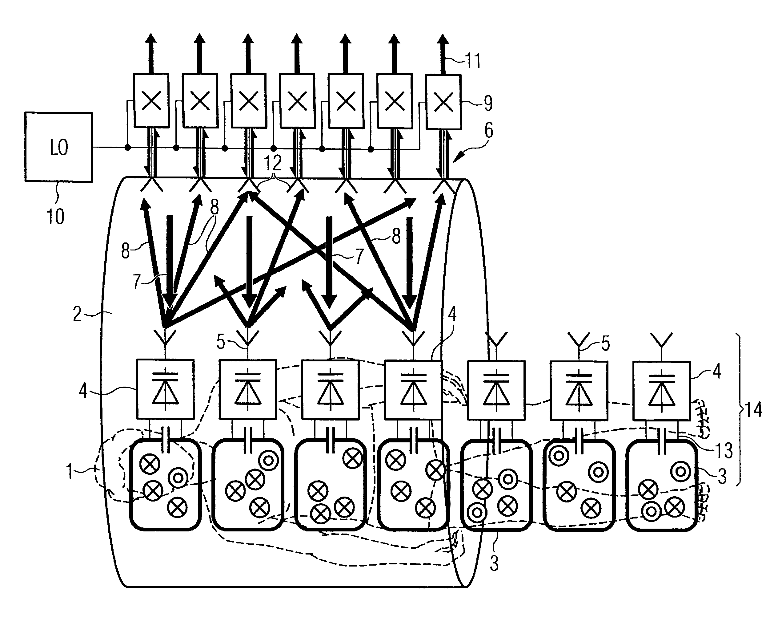
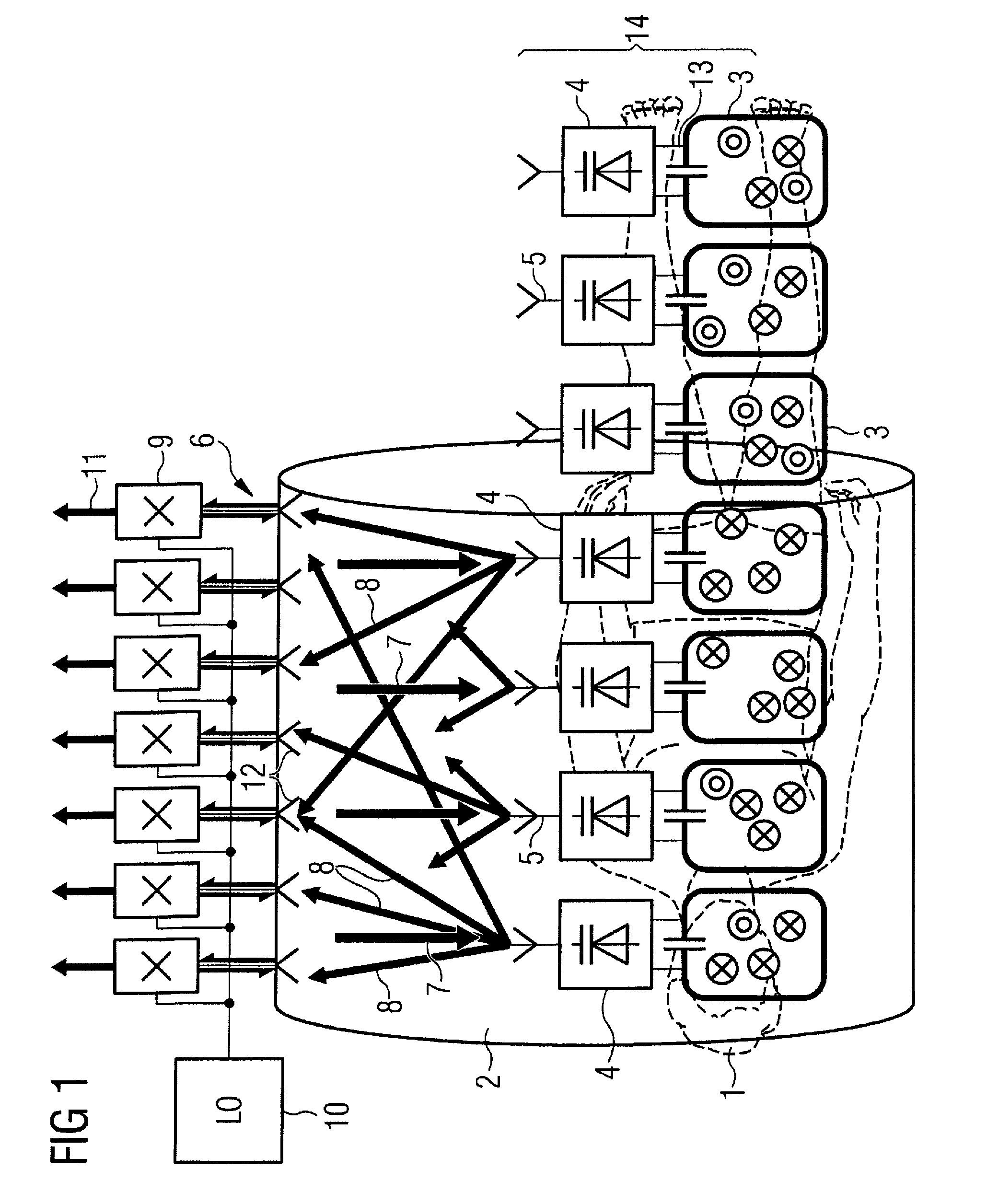
[0033]The wireless concept to which the features of the present invention apply is based on upconversion of the RF (Larmor) frequency signals to microwave frequencies and transmission from local coils located in the patient mat to microwave antennas located on the bore of the scanner. The combination of transmit and receive antennas on the patient and bore respectively constitutes a MIMO (Multiple Input / Multiple Output) system. The greater multiplicity of receive antennas in the bore array allows individual signals from the patient antennas to be resolved. The present invention relates to the bore tube for use in the system described above and in particular to an arrangement of the microwave antenna arrays.

[0034]An example of an MRI system using a MIMO microwave link, suitable for using a bore tube according to the present invention will now be described. However, other architectures are possible and the invention is not limited to the one described below. FIG. 1 shows a patient 1 w...


PUM


Abstract

A wireless magnetic resonance imaging (MRI) scanner bore tube assembly has a radio frequency (RF) antenna, a microwave antenna array and an electrical screen. The RF antenna is formed of a series of RF antenna elements, each comprising a rung. The rungs are spaced at intervals of substantially half of the wavelength of the frequency of operation of the microwave antenna array. The microwave antenna array is formed by a series of microwave antenna elements interleaved between the rungs and the screen acts as a reflector to reflect signals from the microwave antenna elements towards the center of the bore tube.

Description

RELATED APPLICATIONS[0001]The present application is related to the following applications filed simultaneously herewith and respectively having Ser. No. 12 / 612,831, Ser. No. 12 / 612,842, Ser. No. 12 / 612,856, Ser. No. 12 / 613,033 and Ser. No. 12 / 613,082.BACKGROUND OF THE INVENTION[0002]1. Field of the Invention[0003]This invention relates to a wireless magnetic resonance imaging (MRI) scanner bore tube assembly and in particular to an arrangement of microwave dipole antennas of a magnetic resonance imaging (MRI) birdcage antenna using an electrical screen as a reflector.[0004]2. Description of the Prior Art[0005]MRI scanners use a combination of a strong constant magnetic field (B0) from a superconducting magnet which is modified by gradient fields generated by gradient coils, together with a rotating magnetic field (B1) from a radio frequency (RF) antenna to excite nuclear magnetic resonances in the body that generate short term RF signals that are received to build up a tomographic ...

Claims


Application Information

Patent Timeline
Patent Type & Authority Patents(United States)
IPC IPC(8): G01V3/00
CPCG01R33/3415G01R33/345G01R33/3453G01R33/3692G01R33/34007G01R33/34046
Inventor CORK, PETERHUISH, DAVID WILLIAMVESTER, MARKUS
Owner SIEMENS HEALTHCARE GMBH
Why Eureka
Try Eureka