Image processing apparatus
a technology of image processing and apparatus, applied in the field of image processing apparatus, can solve the problems of poor signal-to-noise ratio of video images, large increase in size and cost of circuits, and difficulty in performing correction while following the external world, so as to achieve high-quality image processing without increasing circuit size and calculation siz
- Summary
- Abstract
- Description
- Claims
- Application Information
AI Technical Summary
Benefits of technology
Problems solved by technology
Method used
Image
Examples
embodiment 1
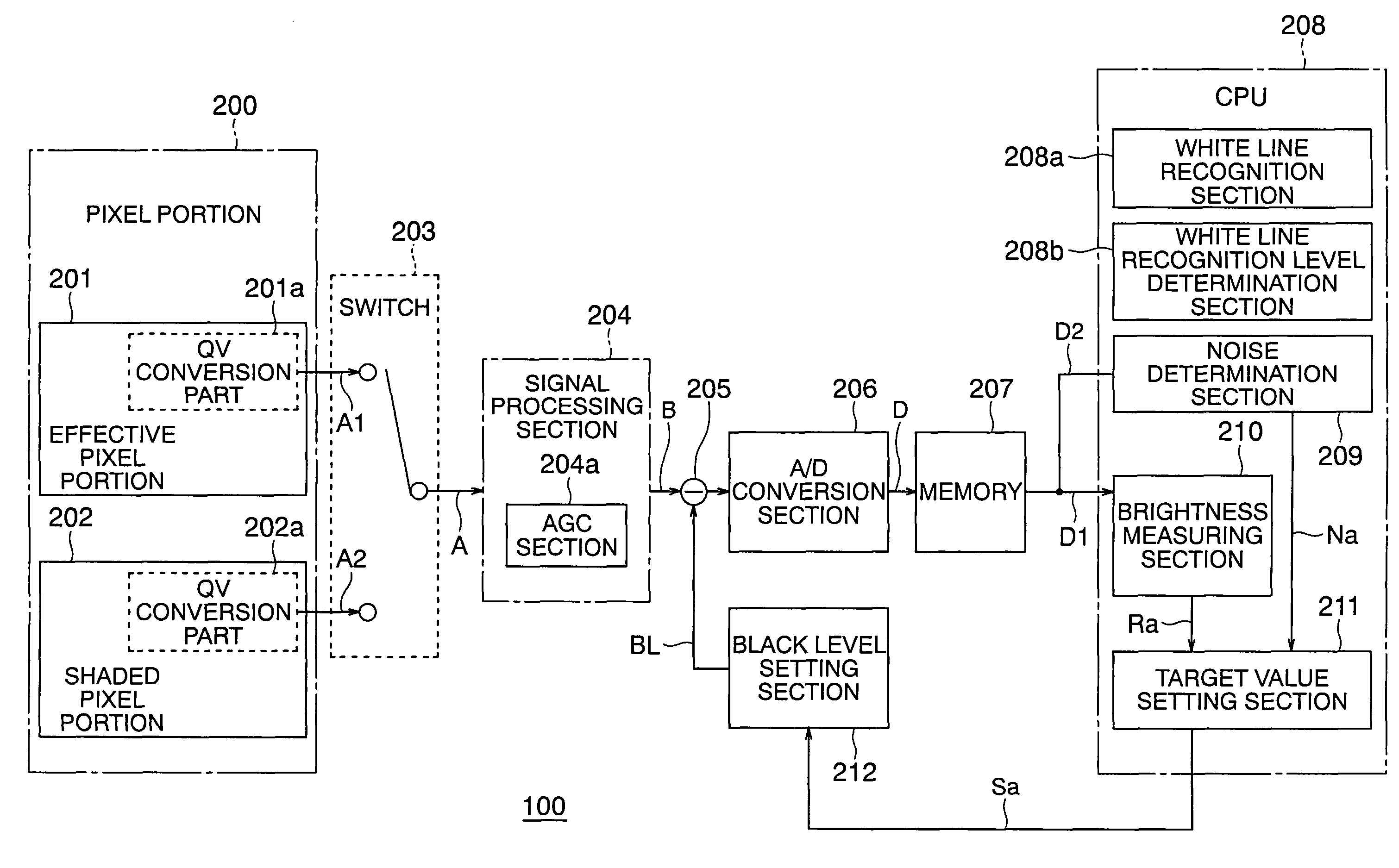
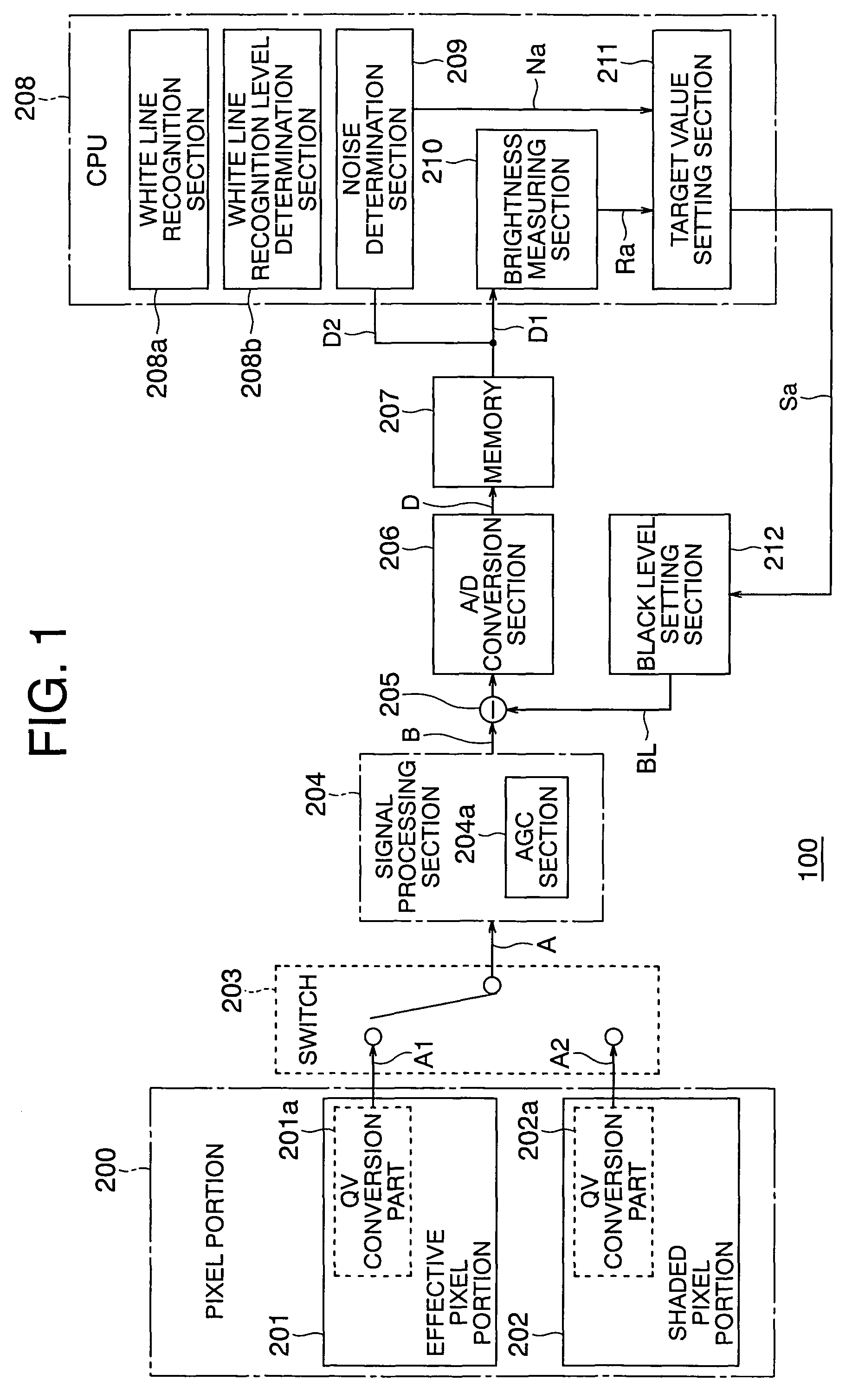
[0036]FIG. 1 is a block diagram that shows the schematic configuration of an image processing apparatus 100 according to a first embodiment of the present invention.
[0037]In FIG. 1, the image processing apparatus 100 includes a pixel portion 200, a switch 203, a signal processing section 204, a subtraction circuit 205, an A / D conversion section 206, a memory 207, a CPU 208, and a black level setting section 212.
[0038]The pixel portion 200 is composed of an image sensor to which a picture taken or picked up by a picture section (not shown) is projected, and has an effective pixel portion 201 and a shaded pixel portion 202.
[0039]The effective pixel portion 201 receives incident light from an unillustrated subject (an object to be sensed or picked up) and accumulates a first electric charge (hereinafter simply referred to as an “electric charge”) corresponding to the amount of light of the incident light.
[0040]On the other hand, the shaded pixel portion 202 accumulates a second electri...
embodiment 2
[0141]In the above-mentioned first embodiment (see FIG. 1 and FIG. 5), the noise determination section 209, the brightness measuring section 210 and the target value setting section 211 are provided in the CPU 208, and the black level target value Sa is set based on the digital output signal D, but as shown in FIG. 12, a noise determination section 209A, a brightness measuring section 210A and a target value setting section 211A may be provided in a signal processing section 204A, and the black level target value Sa may be set based on an analog signal A or an analog output signal B.
[0142]Hereinafter, reference will be made to an image processing apparatus according to a second embodiment of the present invention while referring to FIG. 12.
[0143]FIG. 12. is a block diagram that illustrate the schematic configuration of the image processing apparatus according to the second embodiment of the present invention, wherein the same parts or components. It as those described above (see FIG...
embodiment 3
[0155]Although in the above-mentioned first and second embodiments, the noise level Na is determined based on the data from the shaded pixel portion 202, it may be obtained based on the video signal in the predetermined region W from the effective pixel portion 201.
[0156]Hereinafter, reference will be made to a third embodiment of the present invention in which the noise level Na is set based on the video signal in the predetermined region W.
[0157]The schematic configuration of an image processing apparatus according to the third embodiment of the present invention is as shown in FIG. 1 for example, or the configuration (noise determination section 209A) of FIG. 12 may also be used for this purpose.
[0158]However, note that this embodiment is different from the above-mentioned ones in that the noise determination section 209 calculates the noise level Na not based on data (digital shaded output signal D2) from the shaded pixel portion 202 but based on a video signal (digital video ou...
PUM
 Abstract
Description
Claims
Application Information
 - R&D
- Intellectual Property
- Life Sciences
- Materials
- Tech Scout
- Unparalleled Data Quality
- Higher Quality Content
- 60% Fewer Hallucinations
Browse by: Latest US Patents, China's latest patents, Technical Efficacy Thesaurus, Application Domain, Technology Topic, Popular Technical Reports.
© 2025 PatSnap. All rights reserved.Legal|Privacy policy|Modern Slavery Act Transparency Statement|Sitemap|About US| Contact US: help@patsnap.com


