
Radiographic imaging device, image processing device

a technology of imaging device and image processing device, which is applied in the direction of radio control device, television system, instruments, etc., can solve the problems of reduced image quality, limited imaging timing, and limited imaging timing, and achieve excellent effect and shorten time lag

Active Publication Date: 2012-03-06
FUJIFILM CORP
View PDF13 Cites 16 Cited by
  • Summary
  • Abstract
  • Description
  • Claims
  • Application Information

AI Technical Summary

Benefits of technology

[0012]The present invention is made in consideration of the above problems and an objective thereof is to provide a radiographic imaging device that can capture radiographic images at a specific timing while also shortening the time lag, and an image processing device of the same.
[0035]According to the present invention the excellent effect is obtained that radiographic images can be obtained with a desired timing while shortening the time lag.

Problems solved by technology

If this accumulation extraction operation is stopped midway then a line aberration is generated in the radiographic image at the position at which the extraction operation of the reset mode was stopped, with a reduction in image quality.
However, in the techniques of JP-A No. 2005-13272 and JP-A No. 2005-46203 suffer from the problem that the imaging timing is limited, and there are occasions when a radiographic image cannot be captured at a specific timing.
Namely, in the technique of JP-A No. 2005-13272, imaging can only be performed at a timing in accordance with the notified drive state of the FPD, and the imaging timing is limited.

Method used


Image

  • Radiographic imaging device, image processing device
  • Radiographic imaging device, image processing device
  • Radiographic imaging device, image processing device

Examples


first exemplary embodiment

[0048]Explanation will first be given of a configuration of a radiology information system 10 according to a first exemplary embodiment.

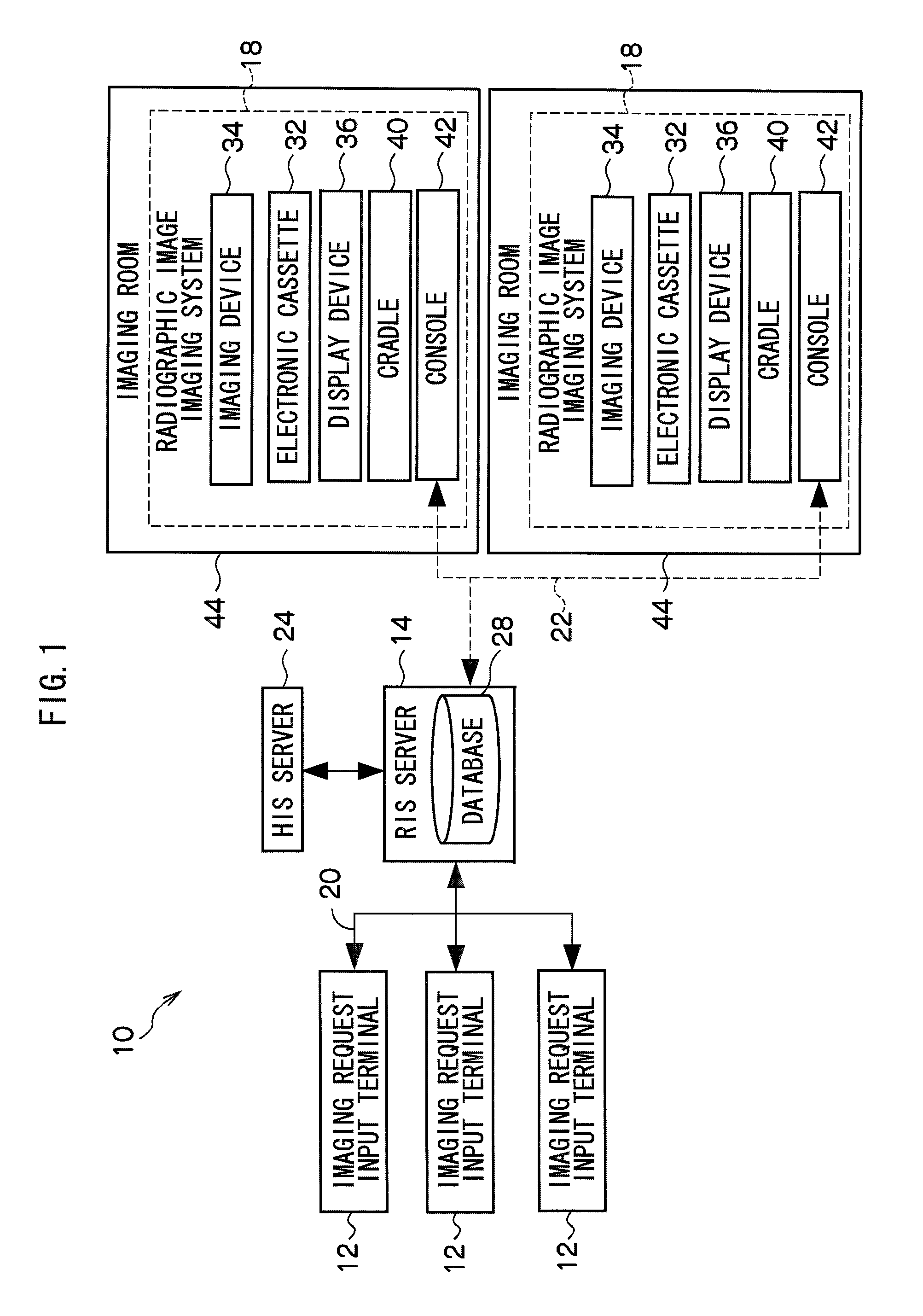
[0049]FIG. 1 shows a block diagram of each essential element of the configuration of a radiology information system 10 (referred to below as RIS 10, RIS: Radiology Information System) according to the present exemplary embodiment.

[0050]The RIS 10 is a system for performing information management in a radiology department, such as management of consultation appointments, consultation records etc., and the RIS 10 configures part of an HIS (Hospital Information System).

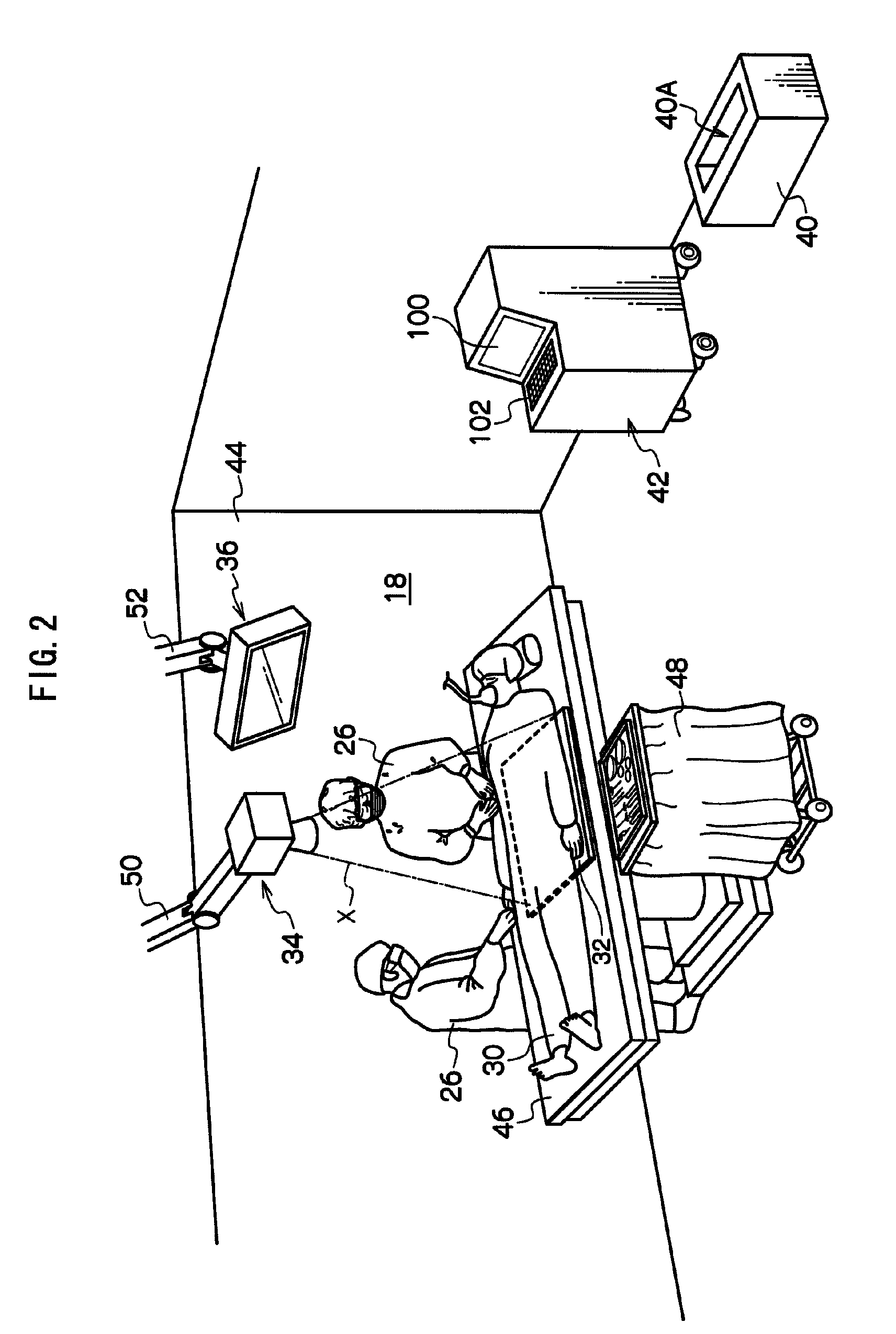
[0051]The RIS 10 is configured including: plural imaging request input terminals 12 (referred to below as input terminals 12); an RIS server 14; and plural radiographic imaging systems 18 (referred to below as imaging systems 18).

[0052]The RIS server 14 is for overall management of the RIS 10, and configuration is made such that each of the input terminals 12 and the imaging systems 18 c...

second exemplary embodiment

[0129]Explanation will now be given of a second exemplary embodiment of the present invention.

[0130]Since the configurations of a radiology information system 10 and a electronic cassette 32 of the second exemplary embodiment are the same as those of the first exemplary embodiment (see FIGS. 1 to 3), explanation thereof will be omitted.

[0131]FIG. 9 shows a block diagram showing a detailed configuration of an imaging system 18 according to the second exemplary embodiment. Similar parts of the configuration to those of the above first exemplary embodiment (FIG. 4) are allocated the same reference numerals and explanation thereof is omitted.

[0132]In the imaging system 18 according to the present exemplary embodiment the electronic cassette 32 and a console 42 have communications capability for wired communication as well as for wireless communication.

[0133]The electronic cassette 32 is provided with a connection terminal 32A for communication with the console 42. The console 42 is prov...


PUM


Abstract

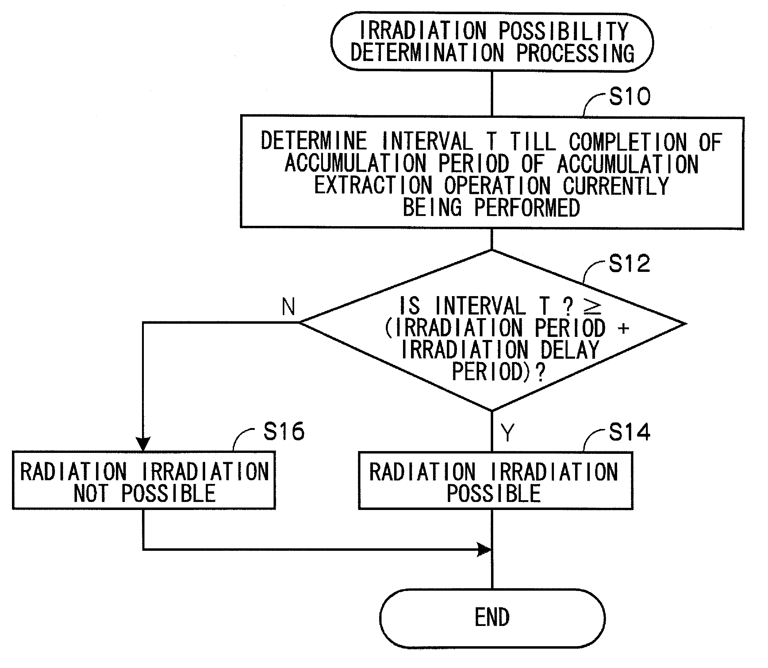
There is provided a radiographic imaging device including: a radiation detector having plural sensor portions; a receiving unit that receives request data requesting radiation irradiation permission from a control device that controls a radiation source; a control unit that controls the radiation detector such that an accumulation extraction operation is repeatedly performed that extracts charge that has accumulated in each sensor portions of the radiation detector, the accumulation extraction operation being performed after a specific accumulation period has elapsed that is greater than the irradiation period of radiation; a determination unit that determines whether or not radiation irradiation of the irradiation period from the radiation source is possible within the accumulation period of the accumulation extraction operation; and a permission unit that permits radiation irradiation if the determination unit has determined that irradiation is possible, and otherwise that permits radiographic image after starting the accumulation period of the next accumulation extraction operation.

Description

CROSS-REFERENCE TO RELATED APPLICATION[0001]This application is based on and claims priority under 35 USC 119 from Japanese Patent Application No. 2008-219933 filed on Aug. 28, 2008 and Japanese Patent Application No. 2009-187410 filed on Aug. 12, 2009, the disclosures of which are incorporated by reference herein.BACKGROUND[0002]1. Technical Field[0003]The present invention relates to a radiographic imaging device and to an image processing device.[0004]2. Related Art[0005]Recently radiation detectors of FPD's (Flat Panel Detectors) etc. that can directly convert radiation into digital data have been put into practice, the FPD's having a radiation sensitive layer disposed on a TFT (Thin Film Transistor) active matrix substrate. Portable radiographic imaging devices (referred to below as “electronic cassettes”) have also recently been put into practice using such FPD's or the like, the portable imaging devices generating image data representing radiographic images of radiation irrad...

Claims


Application Information

Patent Timeline
Patent Type & Authority Patents(United States)
IPC IPC(8): H05G1/08H05G1/64
CPCA61B6/4283A61B6/563A61B6/548H04N5/325H04N5/361H04N5/32H04N25/63
Inventor NISHINO, NAOYUKIKITANO, KOUICHITSUBOTA, KEIJIOHTA, YASUNORIYOSHIDA, YUTAKA
Owner FUJIFILM CORP
Learn More