Surface plasmon polariton direction change device, read/write head, laser-assisted magnetic recording apparatus, and optical circuit

a magnetic recording and direction change technology, applied in the field of surface plasmon polariton direction change devices, read/write heads, laser-assisted magnetic recording apparatuses, optical circuits, can solve the problems of physical interference with another member, difficult to form a film on the metal film, background noise, etc., to prevent the scattering of surface plasmon polariton and high flexibility in design

Inactive Publication Date: 2012-03-13
SHARP KK
View PDF10 Cites 8 Cited by
  • Summary
  • Abstract
  • Description
  • Claims
  • Application Information

AI Technical Summary

Benefits of technology

[0031]According to the metal film 201 disclosed in the Patent Literature 2 out of the conventional techniques, it is necessary to take into consideration an effective refractive index ratio between the first metal film 202 and the second metal film 203 in order to sufficiently change a direction of the surface plasmon polariton 204 at the boundary between the first metal film 202 and the second metal film 203. However, a difference in thickness between the first metal film 202 and the second metal film 203 will inevitably become very large, in a case where it is intended to realize the effective refractive index ratio between the first metal film 202 and the second metal film 203 so that the direction of the surface plasmon polariton 204 is sufficiently changed.

Problems solved by technology

The light thus scattered causes a background noise.
Further, for example, in a case where the metal film 201 which has a step as described above is applied to a laser-assisted magnetic recording apparatus, physical interference with another member is caused due to the step.
Further, it is difficult to form a film on the metal film 201 due to the step.
The scattered light causes a background noise.
Further, for example, in a case where the metal film 201 which has a step as described above is applied to a laser-assisted magnetic recording apparatus, physical interference with another member is caused due to the step.
Further, it is difficult to form a film on the metal film 215 due to the step.

Method used


Image

  • Surface plasmon polariton direction change device, read/write head, laser-assisted magnetic recording apparatus, and optical circuit
  • Surface plasmon polariton direction change device, read/write head, laser-assisted magnetic recording apparatus, and optical circuit
  • Surface plasmon polariton direction change device, read/write head, laser-assisted magnetic recording apparatus, and optical circuit

Examples


embodiment 1

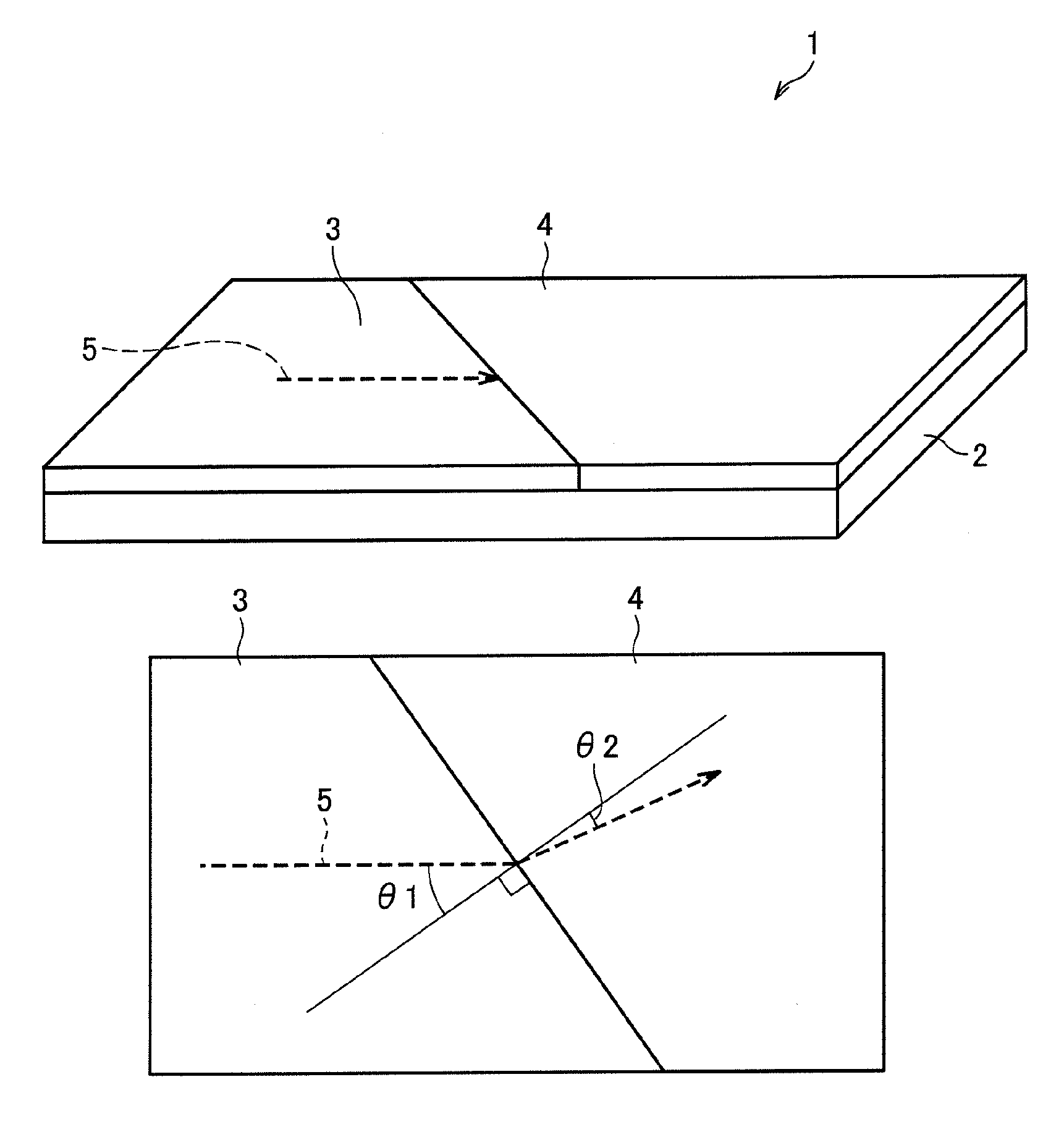
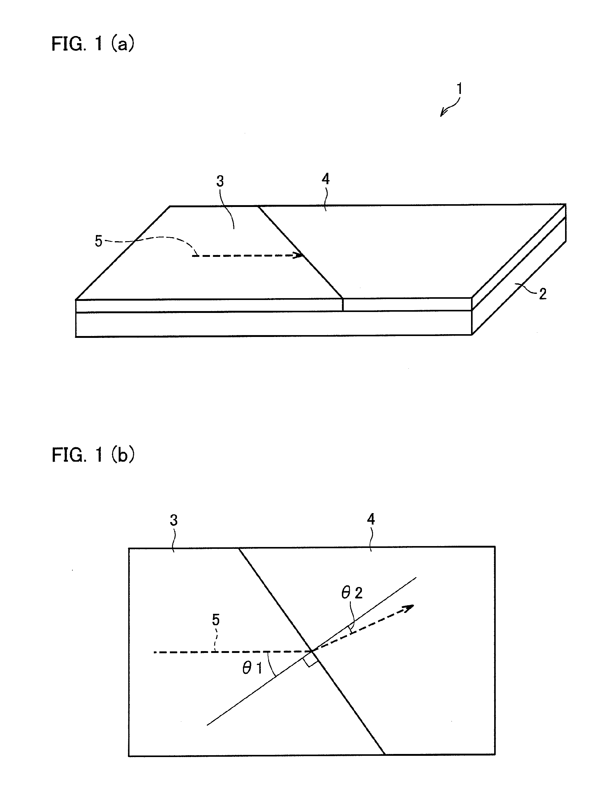
[0078]First, a surface plasmon polariton change device 1 of an Embodiment 1 in accordance with the present invention is described below with reference to FIGS. 1 through 4. FIG. 1 (a) is a perspective view schematically illustrating an arrangement of the surface plasmon polariton direction change device 1 of the present embodiment. FIG. 1 (b) is a plan view illustrating the surface plasmon polariton direction change device 1, and shows that an incident angle and a reflection angle of a surface plasmon polariton to a line perpendicular to a boundary between a first metal film and a second metal film. Note that the arrows shown in FIGS. 1 (a) and 1 (b) indicate a propagation direction of a surface plasmon polariton 5.

[0079]As shown in FIGS. 1 (a) and 1 (b), the surface plasmon polariton direction change device 1 of the present embodiment includes a metal film support member 2, a first metal film 3 and a second metal film 4.

[0080]The surface plasmon polariton direction change device 1 ...

embodiment 2

[0122]The following description deals with a surface plasmon polariton direction change device 11 of an Embodiment 2 of the present invention with reference to FIGS. 5, 6, 23 and 24. FIG. 5 is a perspective view schematically illustrating an arrangement of the surface plasmon polariton direction change device 11 of the Embodiment 2 of the present invention. Constituents which have similar functions to those of the surface plasmon polariton direction change device 1 of the Embodiment 1 are given identical reference numerals.

[0123]In the surface plasmon polariton direction change device 1 of the Embodiment 1 of the present invention, the first metal film 3 and the second metal film 4 are made of different materials so as to have different effective refractive indices. As described above, an effective refractive index of a metal film varies depending on (i) a mode of a surface plasmon polariton 5, (ii) a thickness of the metal film, (iii) a material of which the metal film is made and ...

embodiment 3

[0138]The following description deals with a surface plasmon polariton direction change device 21 of an Embodiment 3 of the present invention with reference to FIG. 7. FIG. 7 is a plan view schematically illustrating an arrangement of the surface plasmon polariton direction change device 21 of the Embodiment 3 of the present invention. Constituents which have similar functions to those of the surface plasmon polariton direction change device 1 of the Embodiment 1 are given identical reference numerals.

[0139]As shown in FIG. 7, the surface plasmon polariton direction change device 21 includes a first metal film 22, a second metal film 23 and a third metal film 24. Each of the first metal film 22, the second metal film 23 and the third metal film 24 is formed on a surface of a metal film support member 2 (not shown).

[0140]The first metal film 22, the second metal film 23 and the third metal film 24 are in contact with each other in this order, and have the same thickness. Further, the...


PUM

PropertyMeasurementUnit
angleaaaaaaaaaa
angleaaaaaaaaaa
refractive indicesaaaaaaaaaa

Abstract

This invention provides a surface plasmon polariton direction change device (1) for changing a propagation direction of a surface plasmon polariton (5). The surface plasmon polariton direction change device (1) includes a metal film support member (2), and a first metal film (3) and a second metal film (4) which are provided on a predetermined surface of the metal film support member (2), are provided adjacently to each other, and are different from each other in effective refractive index. The surface plasmon polariton direction change device (1) is characterized in that the first metal film (3) and the second metal film (4) are provided so that, in at least a part of a boundary between the first metal film (3) and the second metal film (4), an angle θ formed between (i) a line perpendicular to the boundary and (ii) the propagation direction of the surface plasmon polariton (5) satisfies 0°<θ<90° or −90°<θ<0°, and (i) a surface of the first metal film (3) which is opposite to a surface in contact with the metal film support member (2) and (ii) a surface of the second metal film (4) which is opposite to a surface in contact with the metal film support member (2) are flush with each other.

Description

TECHNICAL FIELD[0001]The present invention relates to a surface plasmon polariton direction change device for changing a propagation direction of a surface plasmon polariton which is one kind of near-field light; a read / write head, a laser-assisted magnetic recording apparatus, and an optical circuit which use the surface plasmon polariton direction change device.BACKGROUND ART[0002]It is possible to realize high densities in various technical fields, respectively, by reducing a diameter of so-called a light spot, which is a focal point onto which light is converged. For example, in the field of optical recording, data is recorded and reproduced on and from a recording medium, respectively, with the use of a laser beam. A reduction in diameter of a light spot enables high-density recording / reproducing. Further, in the field of optical fabrication, a material such as a resin or glass is fabricated with the use of a laser beam. A reduction in diameter of a light spot enables a finer f...

Claims


Application Information

Patent Timeline
Patent Type & Authority Patents(United States)
IPC IPC(8): G11B11/00G02B6/10G11B7/135
CPCB82Y10/00B82Y20/00B82Y25/00G11B5/314G11B7/1387G11B11/10536G11B2005/0002G11B2005/0021
Inventor KITAZAWA, TAZUKOONO, TOMOKI
Owner SHARP KK
Why Eureka
Try Eureka