Eureka AIR delivers breakthrough ideas for toughest innovation challenges, trusted by R&D personnel around the world.

Gas turbine fuel nozzle having improved thermal capability

a technology of gas turbine fuel nozzle and thermal capacity, which is applied in the direction of fuel injecting pump, machine/engine, lighting and heating apparatus, etc. it can solve the problems of affecting the overall performance and durability of the engine components, affecting the relative movement of the mating hardware relative to one, and significant wear of the combustion hardware, so as to reduce the thermal stress level of the fuel nozzle and minimize thermal growth. , the effect of reducing the differences in thermal growth

Active Publication Date: 2012-03-20
ANSALDO ENERGIA SWITZERLAND AG
View PDF8 Cites 12 Cited by
  • Summary
  • Abstract
  • Description
  • Claims
  • Application Information

AI Technical Summary

Benefits of technology

[0004]The invention is defined by the claims below, not by this Summary, which is provided to introduce a selection of concepts in a simplified form that are further described below in the Detailed Description. Embodiments of the present invention are directed towards a system and method for, among other things, minimizing thermal growth within a fuel nozzle so as to reduce thermal stress levels in the fuel nozzle.
[0005]The present invention provides embodiments for a fuel nozzle configuration for a gas turbine combustor in which the fuel nozzle receives a heated fluid to elevate the operating temperature of the fuel nozzle so as to reduce the differences in thermal growth of the various fuel nozzle components and reduce thermal stress within the fuel nozzle. In an embodiment of the present invention a fuel nozzle is disclosed comprising an inner tubular member having a centermost passage, an intermediate tubular member surrounding the inner tubular member and forming a secondary passage therebetween, and an outer tubular member surrounding the intermediate tubular member and forming an outer passage. A plurality of injectors extend radially outward from the outer passage for injecting a fuel supply to the combustor from the outer passage while a base end comprises a plurality of feed holes that direct a supply of heating fluid to the secondary passageway. This heating fluid elevates the temperature of the intermediate tubular member to reduce thermal mismatch in the tube between the outer passage and secondary passage. In this embodiment, each of the tubular members are generally cylindrical, except the intermediate tubular member includes a corrugated bellows portion that is used to help compensate for movement caused by thermal growth.
[0006]In an additional embodiment, a fuel nozzle is disclosed comprising an inner tubular member having a centermost passage, an intermediate tubular member surrounding the inner tubular member and forming a secondary passage therebetween, and an outer tubular member surrounding the intermediate tubular member and forming an outer passage. A plurality of injectors extend radially outward from the outer passage for injecting a fuel supply to the combustor from the outer passage while a base end comprises a plurality of feed holes that direct a supply of heating fluid to the secondary passageway to elevate the temperature of the intermediate tubular member to reduce thermal mismatch in the tube between the outer passage and secondary passage. In this embodiment, each of the tubular members are generally cylindrical. In a variation of this embodiment, a shield is placed between the intermediate tubular member and the outer tubular member along a portion of the intermediate tubular member so as to provide a thermal shield to the intermediate tubular member.
[0007]In yet another embodiment of the present invention, a fuel nozzle is disclosed comprising a solid inner tubular member having a centermost passage and a solid outer tubular member surrounding the inner tubular member and forming an outer passage. A plurality of injectors extend radially outward from the outer passage for injecting a fuel supply from the outer passage to a combustor, while a base end comprises a plurality of feed holes that direct a supply of heating fluid to the centermost passageway to elevate the temperature of the inner tubular member to reduce thermal differential in the tube between the outer passage and the centermost passage.
[0008]In a further embodiment, a gas turbine combustor is provided comprising a combustion liner, a cap assembly, and an end cover having a plurality of fuel nozzles that have been previously disclosed. The end cover comprises a plurality of fuel nozzles that extend through openings in the cap assembly such that fuel supplied to the fuel nozzles is injected into the combustor for mixing with compressed air for combustion. Multiple embodiments of the combustor are disclosed in which different embodiments of the fuel nozzle, as previously disclosed, are used. A heating fluid, such as compressed air, is supplied to each of the fuel nozzles through feed holes in each fuel nozzle base. The compressed air elevates the operating temperature of at least one passageway of the fuel nozzle to reduce the thermal gradients in the fuel nozzle and lower thermal stresses caused by large thermal gradients.

Problems solved by technology

There are a number of issues that affect the overall performance and durability of the engine components, especially the combustion section.
By nature, the combustion process creates varying pressure oscillations and dynamics that can result in significant wear to the combustion hardware.
Specifically, the pressure oscillations can cause mating hardware to vibrate and move relative to one another.
Excessive combustion dynamics can cause premature wear of mating hardware such that the hardware must be repaired or replaced.
Since the fuel nozzles are positioned in close proximity to a flamefront in the combustor, the fuel nozzles are exposed to extremely high temperatures.
However, the fuel nozzles carry a fuel having a temperature significantly less than the operating environment, and as a result, the fuel nozzle experiences significant variations in temperature.

Method used


Image

  • Gas turbine fuel nozzle having improved thermal capability
  • Gas turbine fuel nozzle having improved thermal capability
  • Gas turbine fuel nozzle having improved thermal capability

Examples


Embodiment Construction

[0021]The subject matter of the present invention is described with specificity herein to meet statutory requirements. However, the description itself is not intended to limit the scope of this patent. Rather, the inventors have contemplated that the claimed subject matter might also be embodied in other ways, to include different components or combinations of components similar to the ones described in this document, in conjunction with other present or future technologies.

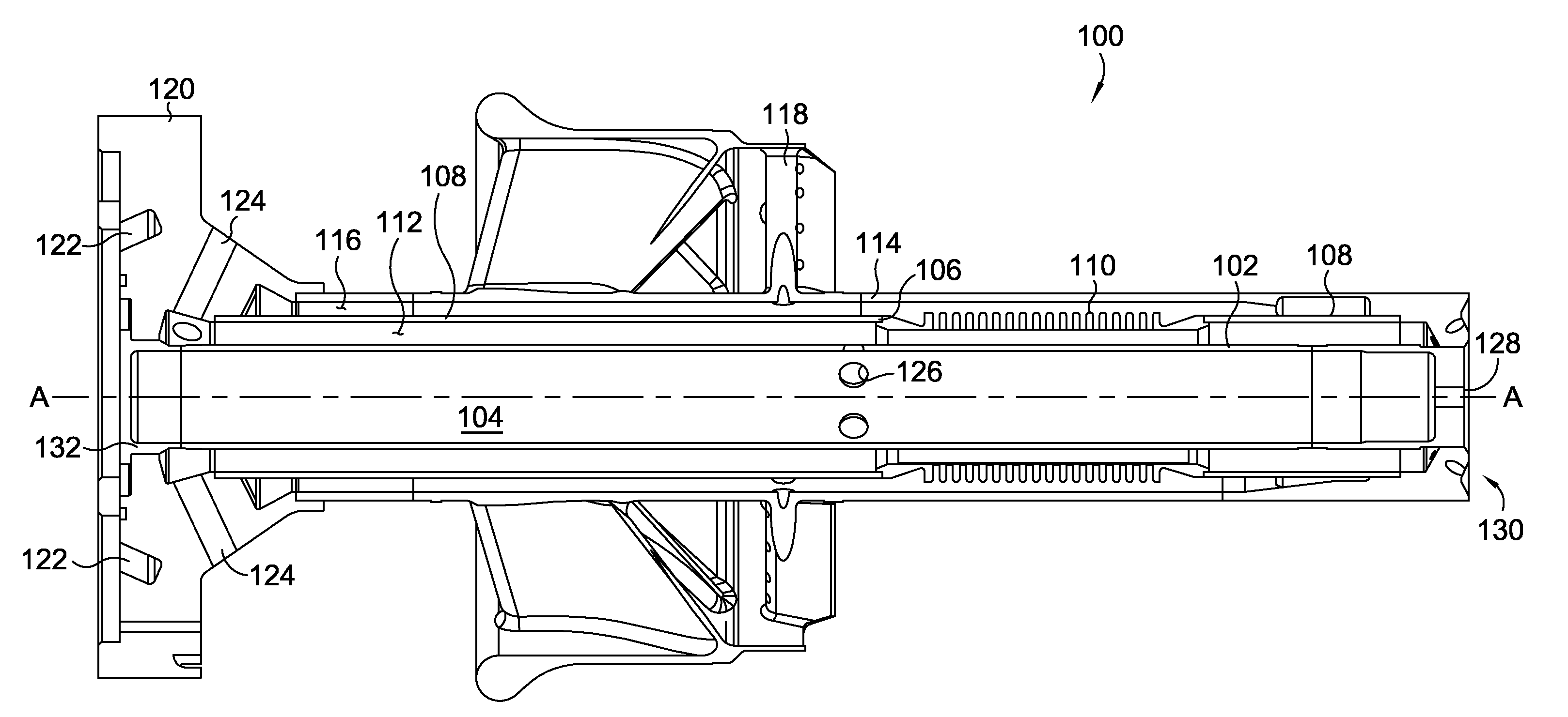
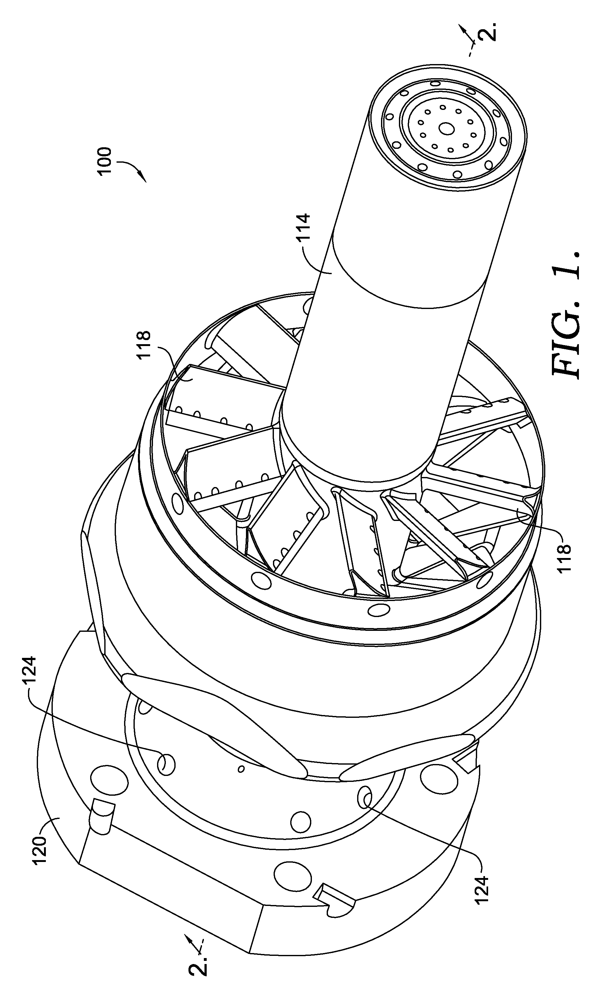
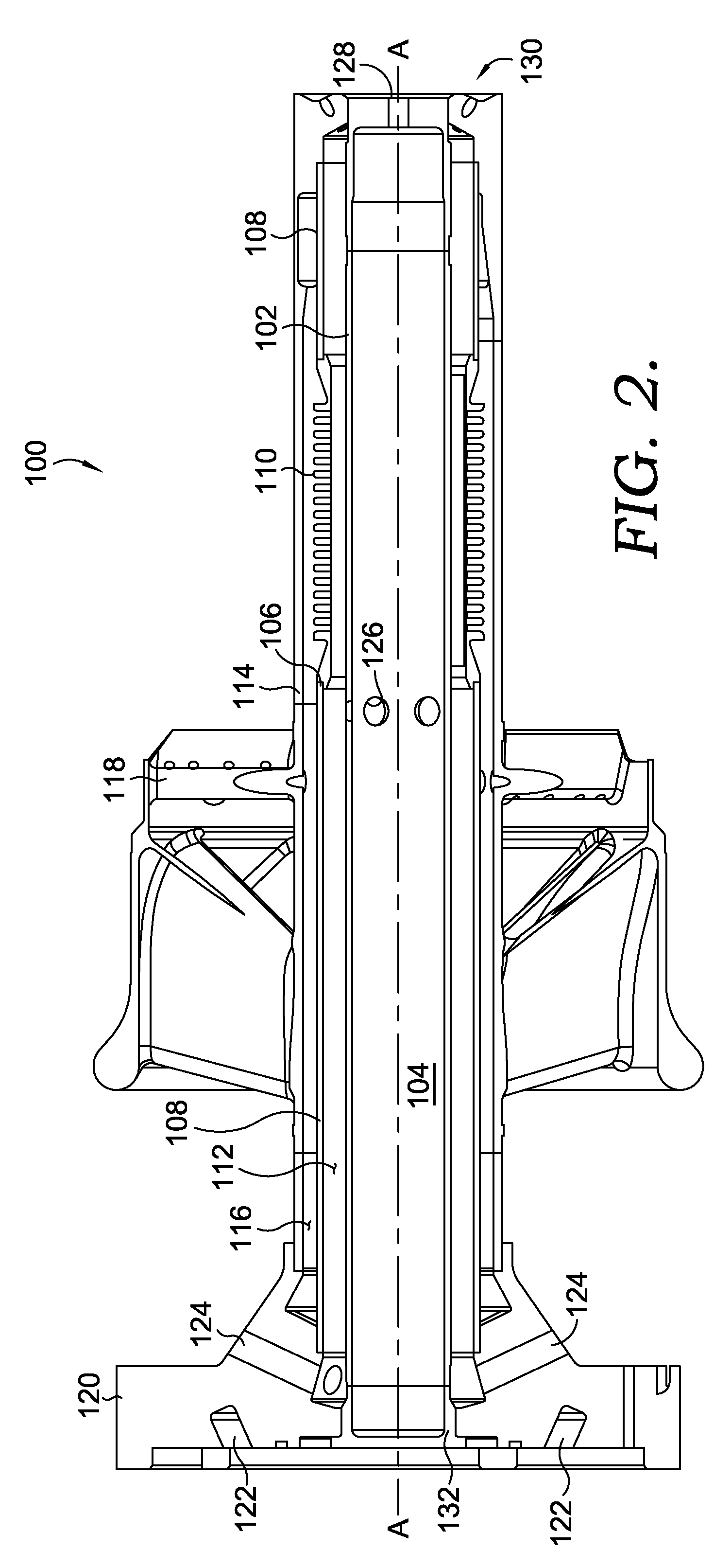
[0022]Referring initially to FIGS. 1 and 2, a fuel nozzle 100 having reduced thermal growth is shown. The fuel nozzle 100 comprises an inner tubular member 102 that is coaxial with a centerline A-A and has a centermost passage 104. Surrounding the inner tubular member 102 is an intermediate tubular member 106. For the embodiment depicted in FIG. 2, the intermediate tubular member 106 has cylindrical portions 108 and a corrugated bellows portion 110. The corrugated bellows portion 110, which is designed to provide...


PUM


Abstract

Embodiments for minimizing relative thermal growth within a fuel nozzle of a gas turbine combustor are disclosed. Fuel nozzle configurations are provided in which a heating fluid is provided to one or more passages in a fuel nozzle from feed holes in the fuel nozzle base. The heating fluid passes through the fuel nozzle, thereby raising the operating temperature of portions of the fuel nozzle to reduce differences in thermal gradients within the fuel nozzle. Various fuel nozzle configurations and passageway geometries are also disclosed.

Description

TECHNICAL FIELD[0001]The present invention relates to gas turbine engines. More particularly, embodiments of the present invention relate to an apparatus for reducing thermal growth differential within a fuel nozzle of a gas turbine combustor.BACKGROUND OF THE INVENTION[0002]Gas turbine engines operate to produce mechanical work or thrust. Specifically, land-based gas turbine engines typically have a generator coupled thereto for the purposes of generating electricity. There are a number of issues that affect the overall performance and durability of the engine components, especially the combustion section. By nature, the combustion process creates varying pressure oscillations and dynamics that can result in significant wear to the combustion hardware. Specifically, the pressure oscillations can cause mating hardware to vibrate and move relative to one another. Excessive combustion dynamics can cause premature wear of mating hardware such that the hardware must be repaired or repla...

Claims


Application Information

Patent Timeline
Patent Type & Authority Patents(United States)
IPC IPC(8): F02C1/00
CPCF23R3/286F23D2900/00008F23R2900/00001F23R2900/00005
Inventor STUTTAFORD, PETERECONOMO, PAULOUMEJJOUD, KHALIDDUFFLOCQ, MAXRIZKALLA, HANY
Owner ANSALDO ENERGIA SWITZERLAND AG
Why Eureka
Eureka Blog
Learn More