Ink jet printing apparatus and ink processing method for same

a technology of ink processing and printing apparatus, which is applied in the field of printers, can solve the problems of inflating bubbles, ejection failure, and getting trapped in bubbles, and achieves the effect of no cumbersome operations and increased running costs

Inactive Publication Date: 2012-03-20
CANON KK
View PDF34 Cites 9 Cited by
  • Summary
  • Abstract
  • Description
  • Claims
  • Application Information

AI Technical Summary

Benefits of technology

[0014]A main object of this invention is to provide a novel mechanism and method for substantially and efficiently adding water directly or indirectly to an ink discharged from a print head (excluding the ink used to form an image) which is in a liquid or viscous state, thereby alleviating the undesirable state of the discharged ink and facilitating ink processing. Another object of this invention is to maintain a desired ink processing performance of a maintenance mechanism, such as a wiping mechanism, or other mechanism for processing ink discharged from the print head in the ink jet printing apparatus, while satisfying the following requirements. The first requirement is that a large space to accommodate a liquid to be supplied to this mechanism is not required; the second is that the user is free from a cumbersome operation or from an increased running cost; and the third is that the ink processing does not depend on environment.
[0021]The invention implemented in any one of the first to sixth aspects concerns the processing of ink coming out of the print head and adhering to the ejection face of the print head, or ink discharged during a preliminary ejection or a suction-based recovery operation, or ink ejected outside an edge of a print medium to perform a marginless printing or edge-to-edge printing on the print medium. During the ink processing or during a preparatory stage, the atmosphere is cooled to produce water, which is directly used. Therefore, no large space to accommodate the maintenance liquid is required; no cumbersome operations or increased running cost are imposed on the user; and a desired ink processing performance can be maintained, unaffected by the environment.

Problems solved by technology

Further, during the ink ejection operation, fine ink droplets (satellite or secondary droplets) may be ejected from the print head in addition to the main ink droplets intended to form an image and may drift in the atmosphere.
The ink that settled around the ejection openings may pull the main ink droplets as they are ejected, deflecting a direction of the ejecting droplets, i.e., interfering with the main ink droplets flying in straight line.
Therefore, when the nozzles in question are used thereafter, the print head may not be able to eject ink stably when applied a normal ink ejection energy, resulting in an ejection failure.
Further, if bubbles exist in ink reservoirs inside the print head, i.e., in the liquid paths on the inner side of the nozzles or in a common chamber communicating with the liquid paths, a gas that has passed through the ejection openings and the interior of a member forming the print head may get trapped in the bubbles which in turn grow in size.
The bubbles may also inflate due to a temperature increase during the printing operation.
These will interfere with normal ink supply from an ink source, causing an ink ejection failure.
Compared with an ink containing dye (dye-based ink), the pigment-based ink is less capable of re-dispersing a colorant after evaporation and has a characteristic that a high molecular compound used to disperse the pigment in a solvent is easily adsorbed to the ejection face.
As a result, the problem (a) may not be alleviated.
Thus, a dry substance of the pigment-based ink whose water content has dried on the ejection face has a greater damaging effect on the ejection face than a dry substance of the dye-based ink which has the colorant itself dissolved at a molecular level.
This problem also occurs in other than the pigment-based ink whenever high molecular compounds exist in the ink as a result of adding a reaction liquid to the ink for adjustment of ink viscosity, for improvement of lightfastness or for other purposes.
These documents, however, offer a very limited description on the nonvolatile solvent.
This technology, however, cannot improve the humidity in the cap when the cooling operation is performed with the nozzles capped.
Conversely, if the cap is cooled before the capping operation, no desirable response can be expected nor can an absolute humidity enough to prevent head clogging be obtained because the cap has a communication tube for discharging ink.
This poses a problem of an increased size of the printer.
Although the size of the printer may be reduced by adopting a construction that the nonvolatile solvent is periodically replenished, the user is required to perform the cumbersome processing.
If a processing liquid available in the market is used, the running cost can increase.
Further, depending on the environment in which the printer is used, the nonvolatile solvent may become dry or wet, changing its property, which in turn results in variations in the amount of solvent applied to the wiper and therefore a possibility of a desired wiping performance failing to be produced.
Further, the Japanese Patent Application Laid-open No. 10-138503 is primarily concerned with the application of the nonvolatile solvent to the wiper and is not aware of the problem that a waste ink introducing portion of an absorbent is blocked by a viscous ink or solidified ink and that this prevents the waste ink from spreading into the interior of the absorbent, resulting in an overflow of the waste ink.
Therefore, the waste ink introducing portion may be blocked, preventing the infiltration of waste ink into the interior of the absorbent, which in turn may result in an overflow of waste ink.

Method used


Image

  • Ink jet printing apparatus and ink processing method for same
  • Ink jet printing apparatus and ink processing method for same
  • Ink jet printing apparatus and ink processing method for same

Examples


first embodiment

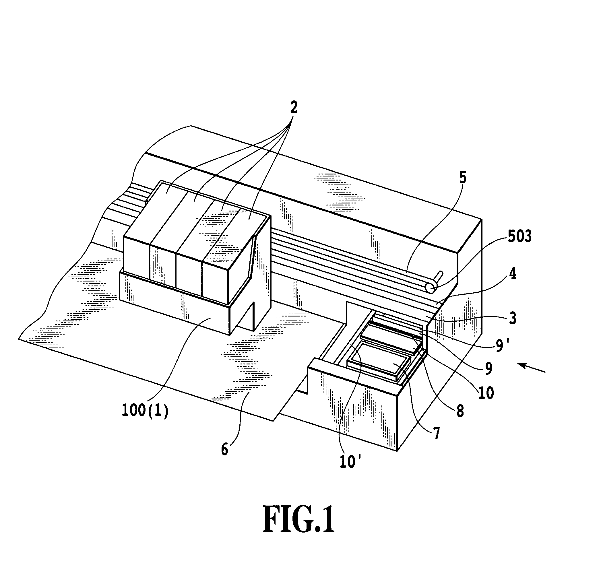
[0043]FIG. 1 is a schematic perspective view showing an essential portion of an ink jet printer according to one embodiment of this invention.

[0044]In the ink jet printing apparatus shown, a carriage 100 is secured to an endless belt 5 and can be moved along a guide shaft 3. The endless belt 5 is wound around a pair of pulleys 503, one of which is coupled to a drive shaft of a carriage drive motor (not shown). Thus, the carriage 100 is reciprocally moved to the left and right along the guide shaft 3 (main scan) in this figure, as the motor is operated.

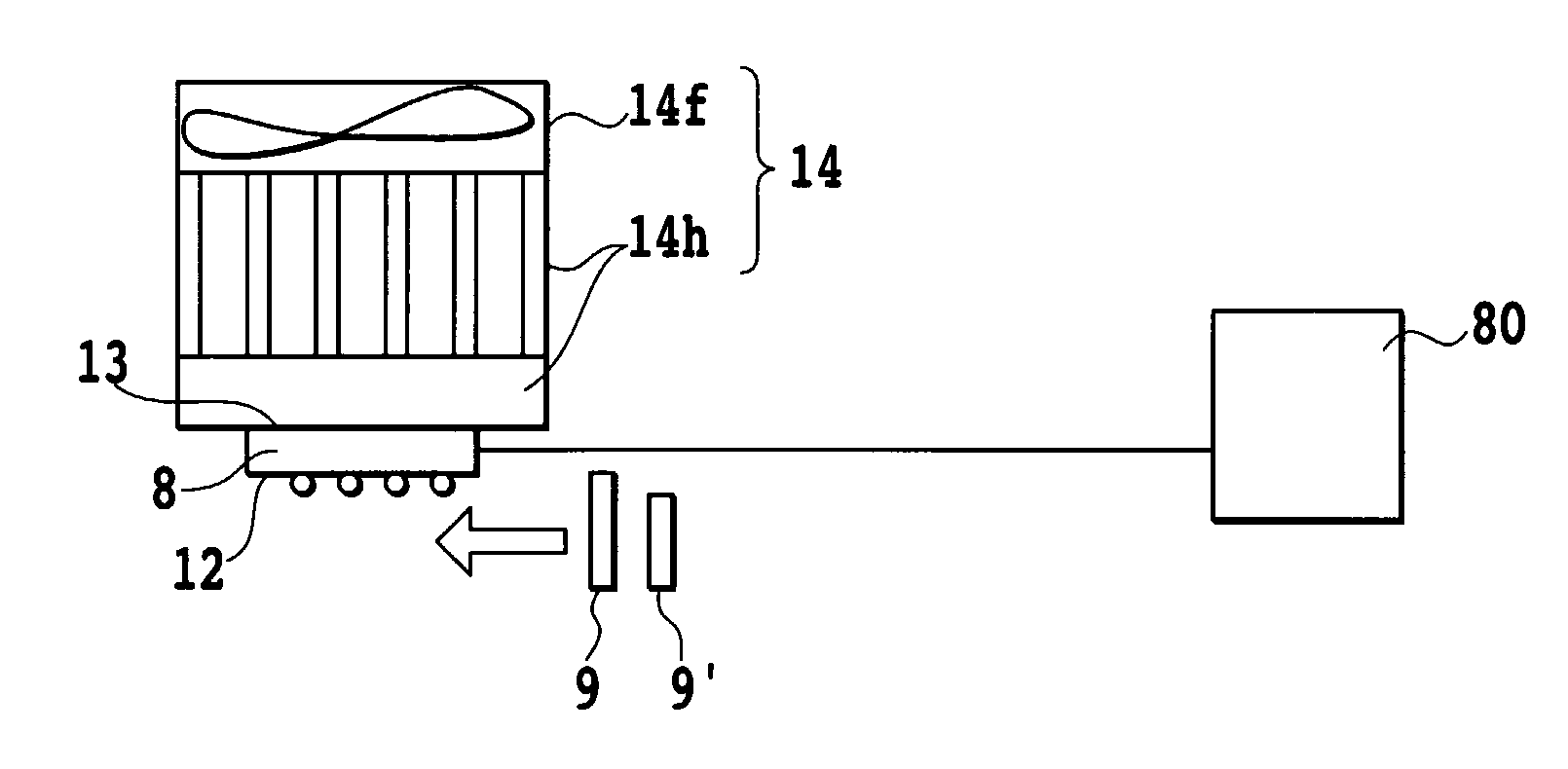
[0045]On the carriage 100 is mounted a print head 1 that removably holds an ink tank 2. The print head 1 has an array of ink ejection nozzles facing a print medium or paper P and arranged in a direction other than a main scan direction (for example, in a sub-scan direction in which the print medium 6 is fed). A set of the nozzle array and the ink tank 2 can be provided in number corresponding to that of ink colors used. In the example ...

second embodiment

[0060]The maintenance mechanism to which this invention can be applied is not limited to the wiper blade that directly contacts the ejection face 11 of the print head 1 as described in the above embodiment. This invention is also applicable to the portion that holds waste ink discharged as a result of preliminary ejection and suction-based recovery operation.

[0061]FIG. 7 is a schematic perspective view showing an essential portion of an ink jet printer according to the second embodiment of the invention. This example has an almost similar construction to that of FIG. 1 and components similar in structure to those of the first embodiment (FIG. 1) are assigned like reference numbers. In the following embodiments, although only one wiper blade (reference number 9) is shown, two of them may of course be provided as in the first embodiment.

[0062]FIGS. 8A and 8B are schematic side views of an essential portion of this embodiment, as seen from the arrow of FIG. 7.

[0063]Two tubes 21 are con...

third embodiment

[0074]The present invention can be applied not only to the maintenance mechanism for keeping the ink ejection performance of the print head 1 in good condition as explained in the first and second embodiments, but also to other means to process ink that has come out of the print head 1.

[0075]FIG. 10 is a schematic perspective view of an essential portion of an ink jet printer according to still another embodiment of this invention. This example has almost the same construction as that of FIG. 1 and components that are similar in construction to those of the first embodiment (FIG. 1) are assigned like reference numbers. Further, FIG. 11 is a schematic side cross-sectional view, as seen from the direction of arrow in FIG. 10.

[0076]In these figures, reference numbers 38 and 39 represent a pair of transport rollers provided on an upstream side in a transport path of a print medium 6. Denoted 36 is a platen to support the print medium 6 in an area facing the ejection face 11 of the print...


PUM


Abstract

In an ink jet print head formed with ejection nozzles, which may use a wiping member to wipe ink adhered to the surface of the ink jet print head, it is desired to be able to perform a wiping operation in any environment without requiring a large amount of space to accommodate the liquid used during the wiping operation. To this end, a cooling unit is used which can produce water by cooling the atmosphere. This cooling unit is operated to produce water, which is brought into contact with and transferred onto the wiping member before the wiping member performs wiping.

Description

TECHNICAL FIELD[0001]The present invention relates to a printer for industrial and home use using a commercially available aqueous ink (ink containing a colorant such as dye, pigment and dye-pigment mixture and ink not containing these). More particularly, the present invention relates to an ink jet printing apparatus suitably used as the above printer and to an ink processing method for the ink jet printing apparatus. The invention further relates to a technique suitably applied to the ink processing performed during a maintenance of the printing apparatus.BACKGROUND ART[0002]The ink jet printing system suitably applicable to industrial and home use printers using the above aqueous ink is a system that transforms input image data into an output image by means of a liquid ink. A technique for maintaining performance of an ink ejecting print head is important from the standpoint of reliability of a printing operation and is employed for the following reasons.[0003](a) An ink ejection...

Claims


Application Information

Patent Timeline
Patent Type & Authority Patents(United States)
IPC IPC(8): B41J29/377
CPCB41J2/16552B41J29/377
Inventor OGASAWARA, MASASHISANADA, MIKIO
Owner CANON KK
Why Eureka
Try Eureka