Exhaust system device with mounting bracket

a technology for mounting brackets and exhaust systems, which is applied in auxillary pretreatment, separation processes, applications, etc., can solve the problems of affecting the performance of non-exhaust treatment devices, or both, and preventing the air cleaner from the muffler

Active Publication Date: 2012-03-27
CATERPILLAR INC
View PDF9 Cites 42 Cited by
  • Summary
  • Abstract
  • Description
  • Claims
  • Application Information

AI Technical Summary

Problems solved by technology

However, due to the increasing complexity and number of exhaust treatment devices and the small amount of available space, mounting and interconnecting exhaust treatment devices has proven difficult.
However, the high temperatures created by the exhaust treatment system may damage or diminish performance of the non-exhaust treatment devices, their related systems, or both.
Although the system of the '849 patent may disclose a combined engine and muffler compartment with a shield section, the '849 system may only protect the air cleaner from the muffler and not other exhaust system components.
Furthermore, the '849 system may not provide an integrated, compact, and cost-effective mounting solution.

Method used


Image

  • Exhaust system device with mounting bracket
  • Exhaust system device with mounting bracket
  • Exhaust system device with mounting bracket

Examples


Embodiment Construction

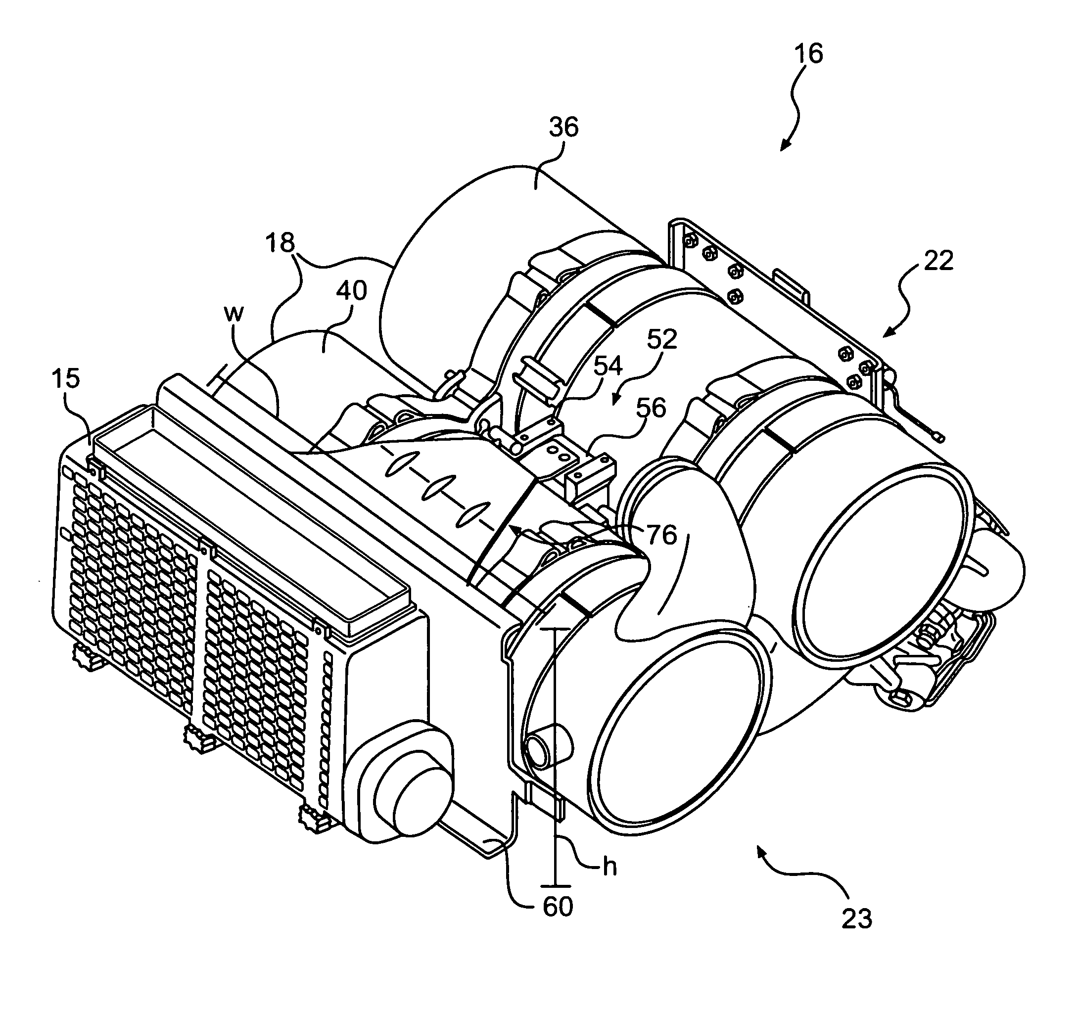
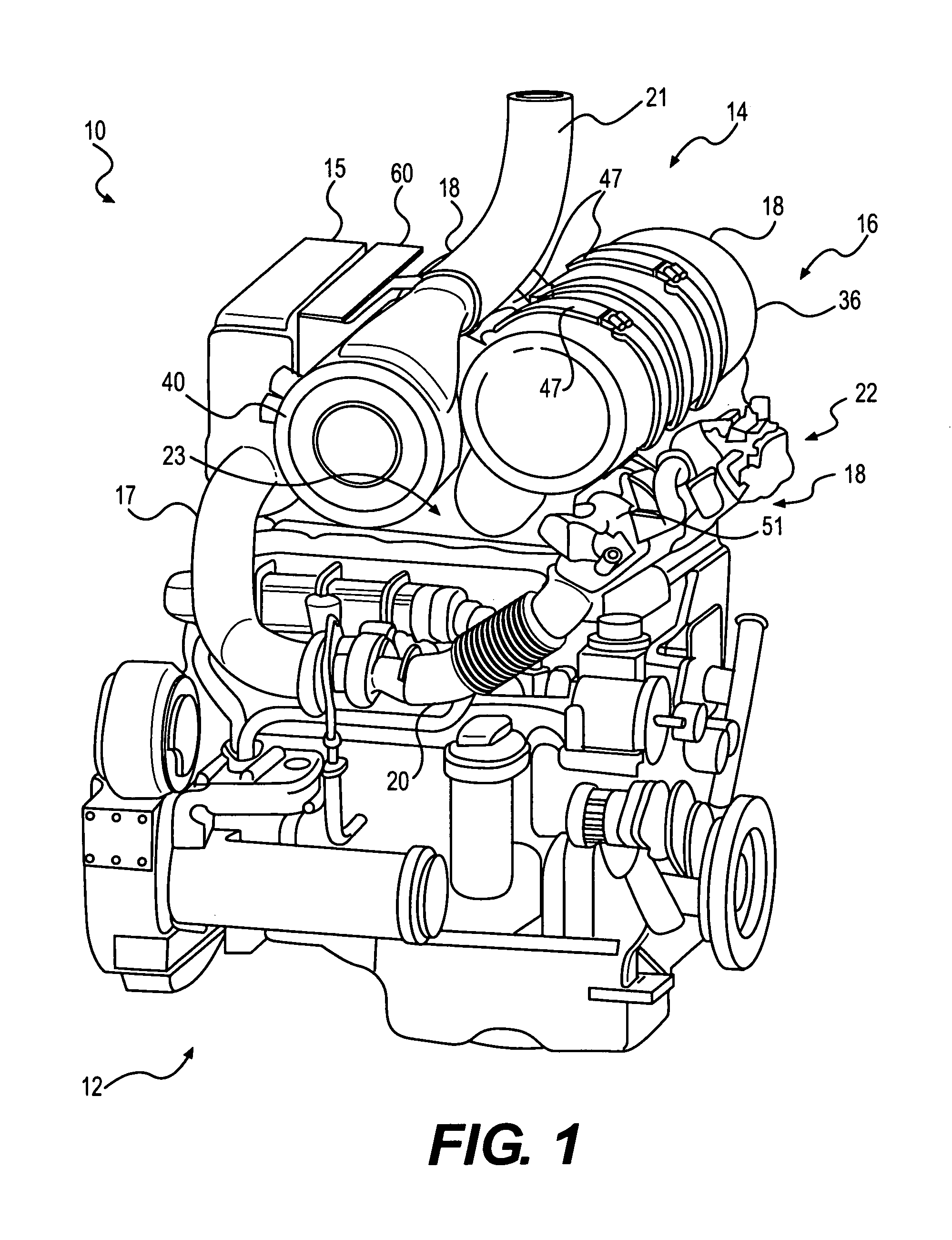
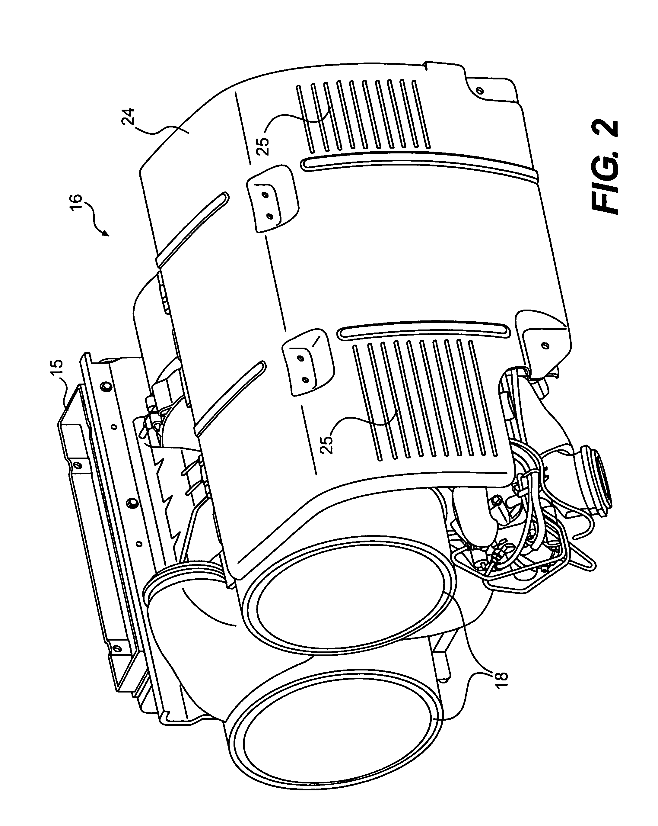
[0015]FIG. 1 illustrates a diagrammatic representation of a power system 10, which may include a power source 12 and an exhaust system 14. Power source 12 may embody a combustion engine, such as, for example, a diesel engine, a gasoline engine, a gaseous fuel-powered engine (e.g., a natural gas engine), or any other type of combustion engine known to one skilled in the art. Power source 12 may have a plurality of combustion chambers (not shown) that convert potential chemical energy (usually in the form of a combustible gas) into useful mechanical work. It is also considered that power source 12 may embody a furnace or a similar device. Power source 12 may receive air from an air cleaner 15 which fluidly communicates with power source 12 via intake 17.

[0016]Air cleaner 15 may be a device used to prevent particulates and other impurities in the air from entering power source 12. Air cleaner 15 may have filtering elements (not shown) composed of paper, foam, cotton, and / or other natur...


PUM

PropertyMeasurementUnit
widthaaaaaaaaaa
heightaaaaaaaaaa
temperaturesaaaaaaaaaa

Abstract

An exhaust system device is disclosed. The exhaust system device may have a mount supporting a first exhaust treatment device and a second exhaust treatment device. The exhaust system device may also have a mounting bracket coupled to the mount. The exhaust system device may further have an air cleaner attached to the mounting bracket. The mounting bracket may be configured to substantially occlude the air cleaner from thermal radiation emitted by the first exhaust treatment device and the second exhaust treatment device.

Description

TECHNICAL FIELD[0001]The present disclosure relates generally to a bracket for mounting an air cleaner and, more particularly, to a bracket configured to mount an air cleaner in an exhaust system.BACKGROUND[0002]Conventional diesel powered systems for engines, factories, and power plants produce emissions that contain a variety of pollutants. These pollutants may include, for example, particulate matter (e.g., soot), nitrogen oxides (NOx), and sulfur compounds. Due to heightened environmental concerns, engine exhaust emission standards have become increasingly stringent. In order to comply with emission standards, machine manufacturers have developed and implemented a variety of exhaust treatment devices to reduce pollutants in exhaust gas prior to the exhaust gas being released into the atmosphere. The exhaust treatment devices may include, for example, a diesel particulate filter, a selective catalytic reduction device, a diesel oxidation catalyst, a fuel-fired burner for regenera...

Claims


Application Information

Patent Timeline
Patent Type & Authority Patents(United States)
IPC IPC(8): F02B67/00F02B77/04
CPCF01N13/1805F01N13/009F02M35/04F02M35/1015F02M35/10268F01N13/1822F01N3/025F01N3/0807F01N3/2066F01N2260/20
Inventor OLSEN, PAUL FREDERICKMERCHANT, JACK ALBERTCHARLES, ERIC JAMESTRICHIRAPALLI, MUTHUKUMAR CHANDRASEKARAN
Owner CATERPILLAR INC
Why Eureka
Try Eureka