Fluid control

a technology of fluid pressure and control, which is applied in the direction of manufacturing tools, welding apparatus, other domestic objects, etc., can solve the problems of accelerating erosion and fraction of energy being dissipated, and achieve the effects of reducing erosion, reducing pressure in a very small volume, and reducing wall erosion

a technology of fluid pressure and control, which is applied in the direction of manufacturing tools, welding apparatus, other domestic objects, etc., can solve the problems of accelerating erosion and fraction of energy being dissipated, and achieve the effects of reducing erosion, reducing pressure in a very small volume, and reducing wall erosion

US8141586B2Active Publication Date: 2012-03-27IMI VISION LTD

Image

  • Fluid control
  • Fluid control
  • Fluid control

Examples


Embodiment Construction

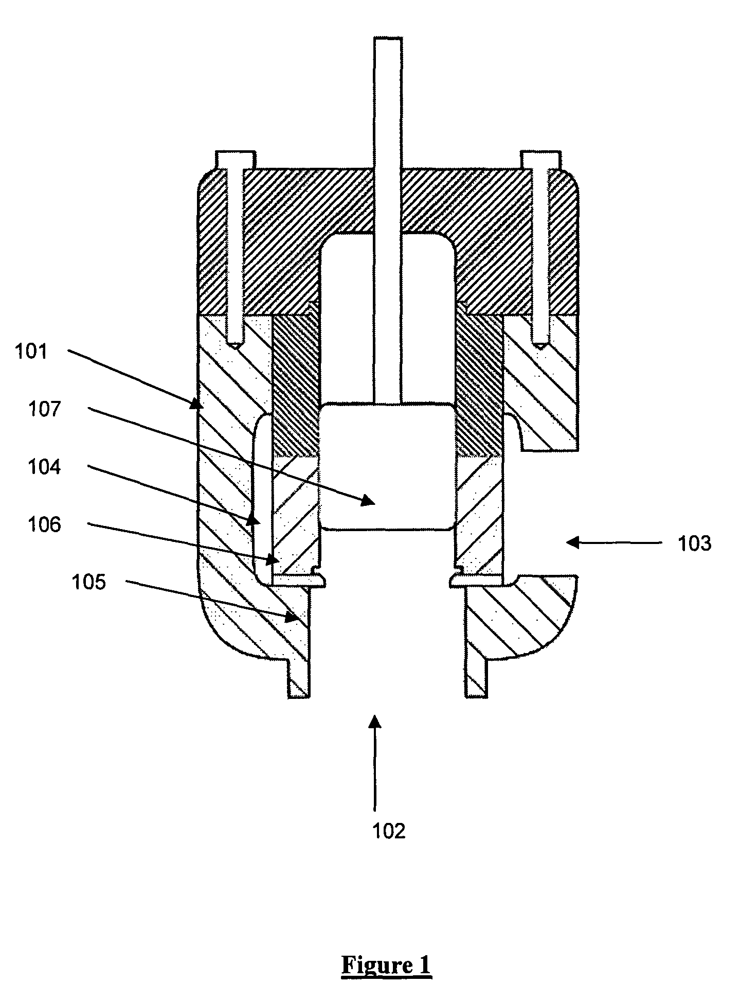
[0048]Referring to FIG. 1 an example of a valve trim in a fluid control valve is shown as common in the art comprising a valve body 101 with an inlet 102 and outlet 103 in fluid communication with one another via a central chamber 104 containing seat ring 105, valve trim 106 and plug 107. When the valve plug 107 sits on the valve seat ring 105 no flow is permitted to pass through the valve. As the plug 107 is lifted in a controlled movement, flow is allowed to enter the valve through inlet 102 and passes through the valve trim 106, which reduces the fluid pressure, and out of outlet 103.

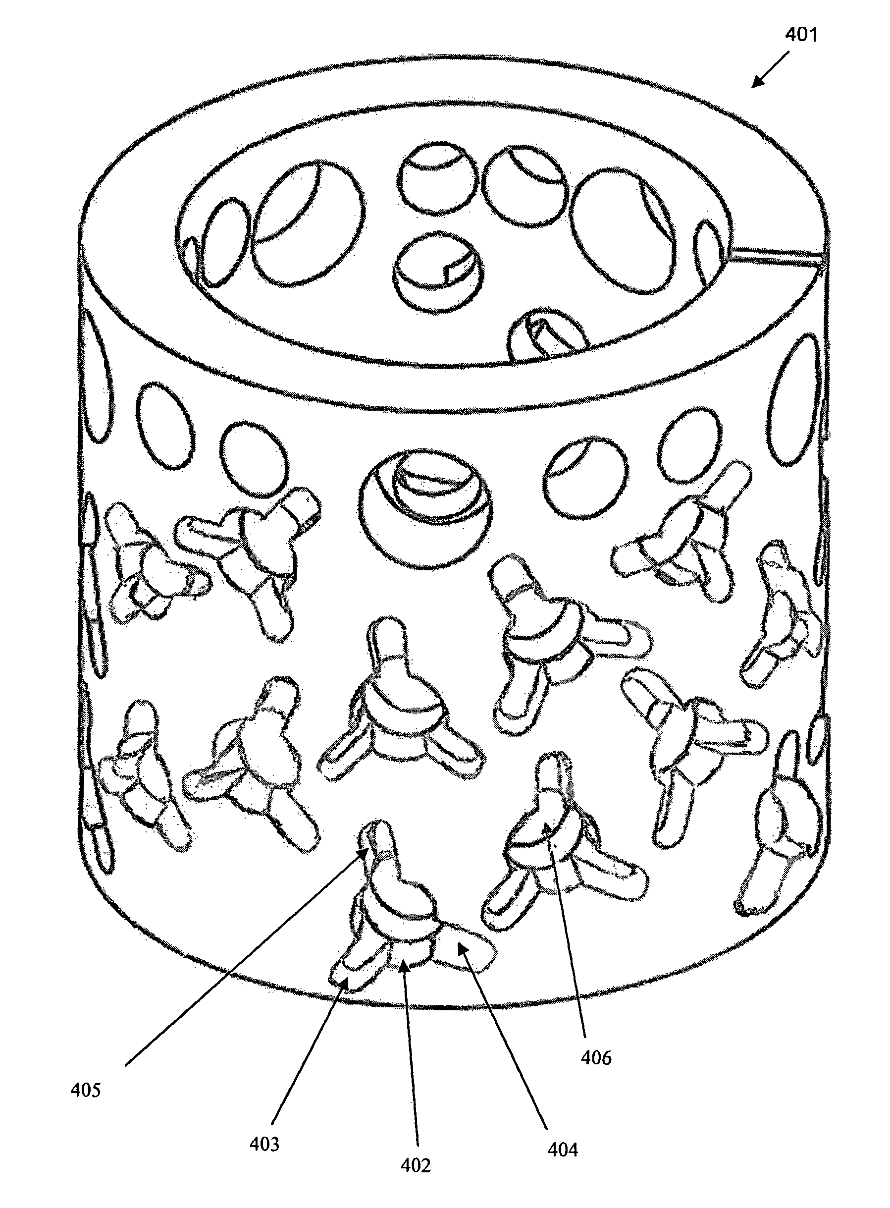
[0049]The trim 106 has a plurality of flowpaths therethrough which have a resistance to flow.

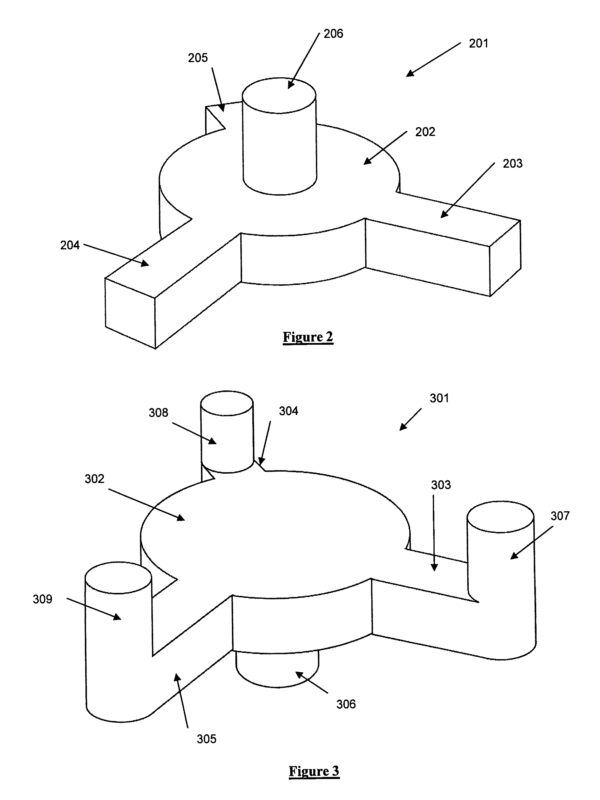
[0050]Referring to FIG. 2 a impingement flowpath 201 is shown comprising a central impingement chamber 202 and having three radial inlet passages 203, 204, 205. As the fluid flows through the inlet passages 203, 204, 205 and enters the impingement chamber 202 the flows start to turn and impinge upon one anoth...


PUM

PropertyMeasurementUnit
flow resistanceaaaaaaaaaa
resistanceaaaaaaaaaa
outer diameteraaaaaaaaaa

Abstract

A valve having a trim comprising a plurality of impingement flowpaths, each flowpath comprising a central impingement chamber and having three radially directed inlet passages is provided. As the fluid floes through the inlet passages and enters the impingement chamber the flow starts to turn and impinge upon one another at a substantially central point within the impingement chamber and exit together via the outlet which is substantially axial to the impingement chamber. As the flows entering the impingement chamber impinge on one another as opposed to a wall of the flowpath, the impingement can be used to create a flowpath with reduced erosion.

Description

CROSS-REFERENCE TO RELATED APPLICATIONS[0001]The present application claims priority to International Application No. PCT / GB2007 / 003480 which was filed on Sep. 14, 2007 and claims priority to Great Britain Patent Application No. 0618166.3 filed on Sep. 15, 2006.STATEMENT RE: FEDERALLY SPONSORED RESEARCH / DEVELOPMENT[0002]Not ApplicableBACKGROUND OF THE INVENTION[0003]1. Technical Field of the Invention[0004]This invention relates to the control and reduction of fluid pressure in control valves, especially but not exclusively severe service valves for use in power industries and oil and gas wells.[0005]2. Description of the Related Art[0006]The technology most widely used in severe service valves utilizes pressure letdown chambers consisting of one or more flow passages containing multiple orifice openings, labyrinths, or multiple, abrupt angular turn, passageways resulting in a staged pressure reduction. Alternatively, flow restrictions can be afforded by providing in the flow passag...

Claims


Application Information

Patent Timeline
27 Mar 2012
Publication
US8141586B2
IPC
F16K3/34
CPC
F16K47/10; Y10T29/49405; Y10T137/86759
Inventors
STEPANOV, EUGENE V.; GOULET, DOUGLAS P.