Method and apparatus for constructing a contact lens with optics

a technology of optics and contact lenses, applied in the field of optics, can solve the problems of unattractive solutions, large system, unsuitable applications, etc., and achieve the effect of widening the viewing angl

Active Publication Date: 2012-03-27
INNOVEGA
View PDF43 Cites 162 Cited by
  • Summary
  • Abstract
  • Description
  • Claims
  • Application Information

AI Technical Summary

Benefits of technology

[0009]For some embodiments described herein, the lenslet may be a refractive lens or a diffractive lens. For further embodiments described herein, the lenslet may be substantially wider in a horizontal direction than in a vertical direction, thereby enabling wider viewing angles in the horizontal direction.

Problems solved by technology

Current systems for optical processing of display information provided by a head-mounted display and non-display information provided by objects other than the head-mounted display have characteristics that make them unattractive solutions for many applications.
Such systems tend to be large, bulky and ill suited for applications where little space is available for processing the display information and the non-display information.
For example, such systems are unattractive solutions for processing display and non-display information in a fighter pilot's helmet where the space for the optical system is limited.

Method used


Image

  • Method and apparatus for constructing a contact lens with optics
  • Method and apparatus for constructing a contact lens with optics
  • Method and apparatus for constructing a contact lens with optics

Examples


Embodiment Construction

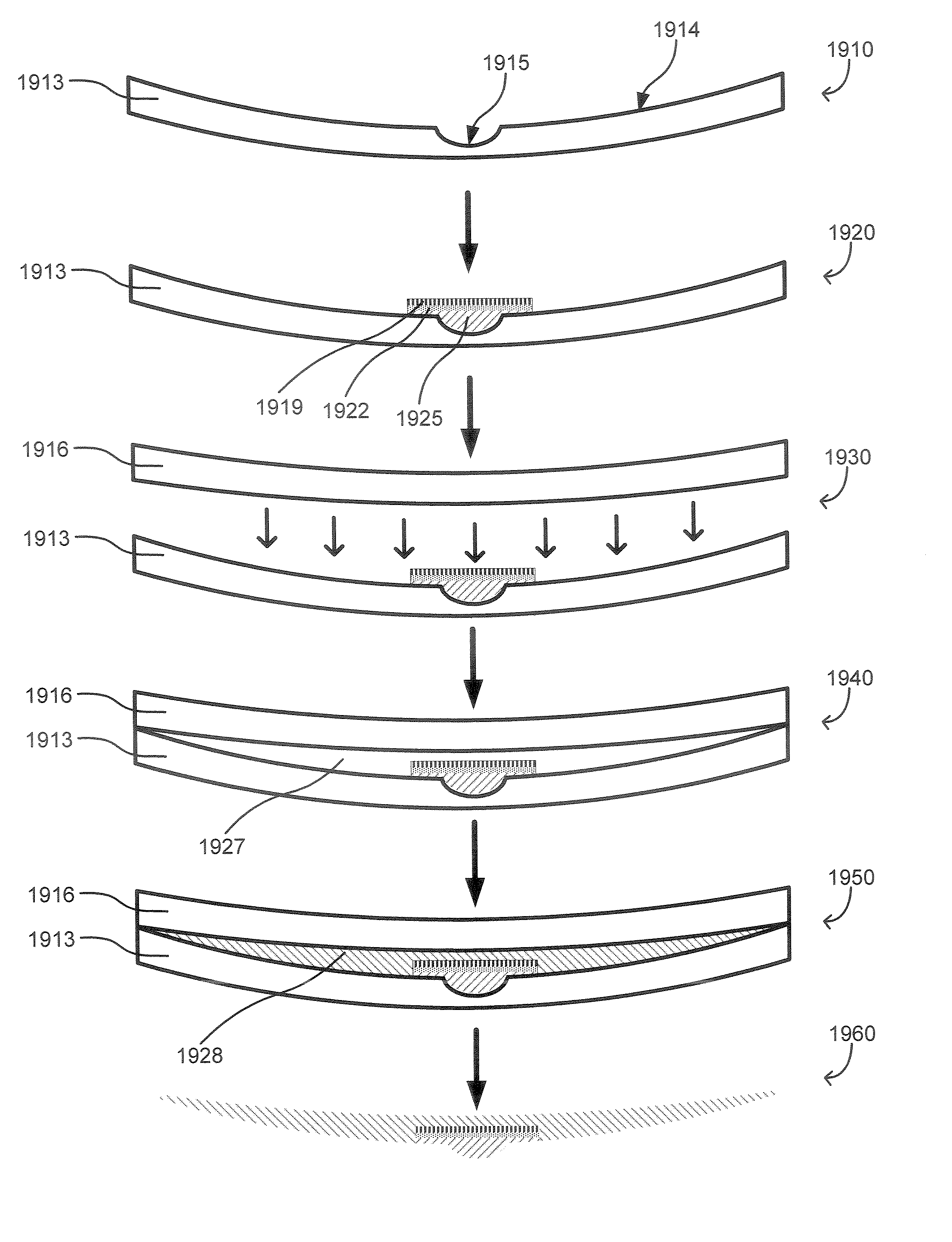
[0004]Various embodiments of the present invention provide systems, methods, and processes for constructing a contact lens.

[0005]In one embodiment, a contact lens assembly is provided, comprising: a curved polymer polarizer with an aperture; a lenslet disposed inside the aperture, wherein the lenslet enables imaging near objects; and a narrow band optical bandpass filter attached to the lenslet.

[0006]In another embodiment, a contact lens assembly is provided, comprising: a curved polymer polarizer having an aperture and a first polarization; a second polymer polarizer having a second polarization; and a lenslet disposed inside the aperture for imaging near objects.

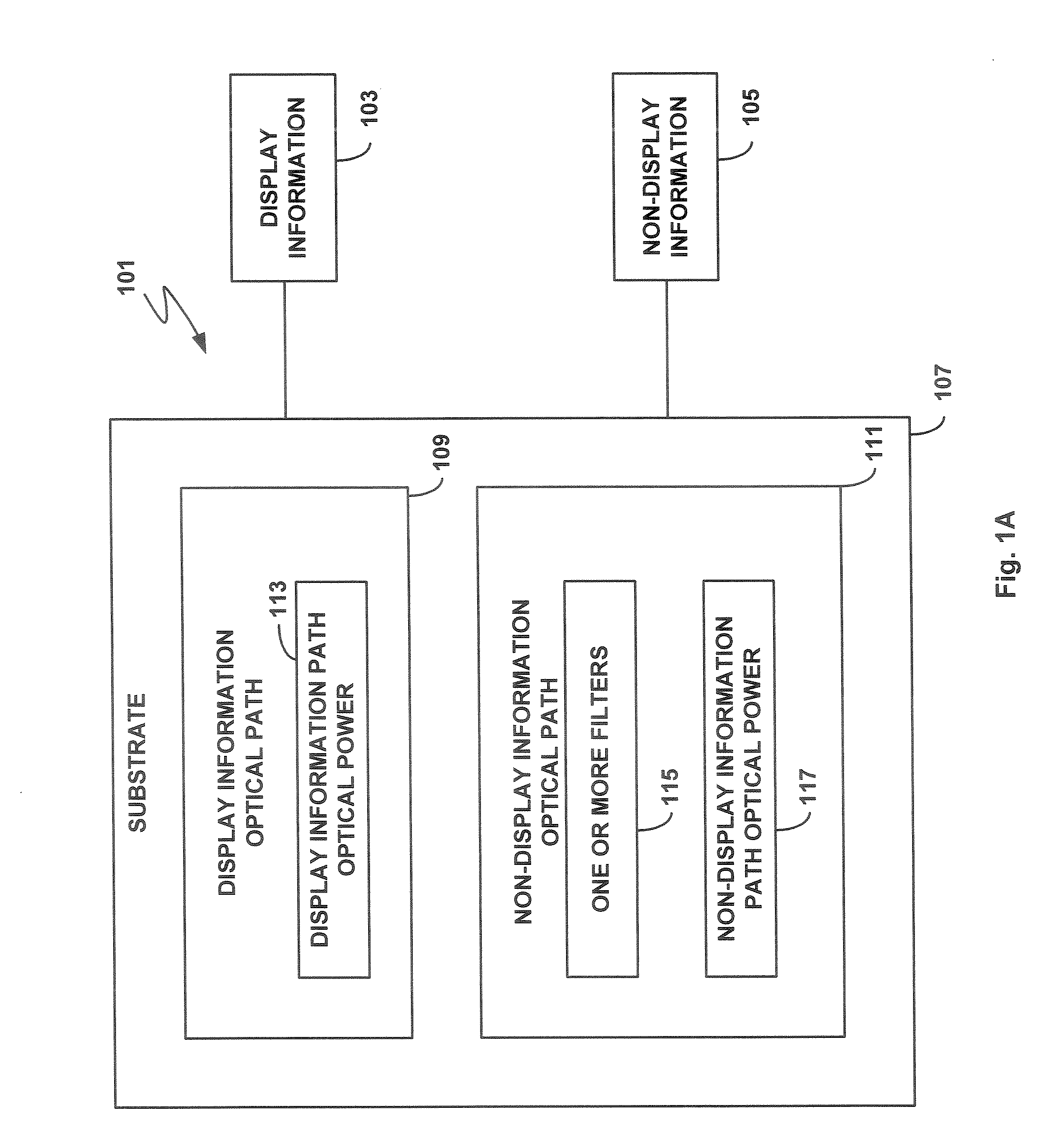
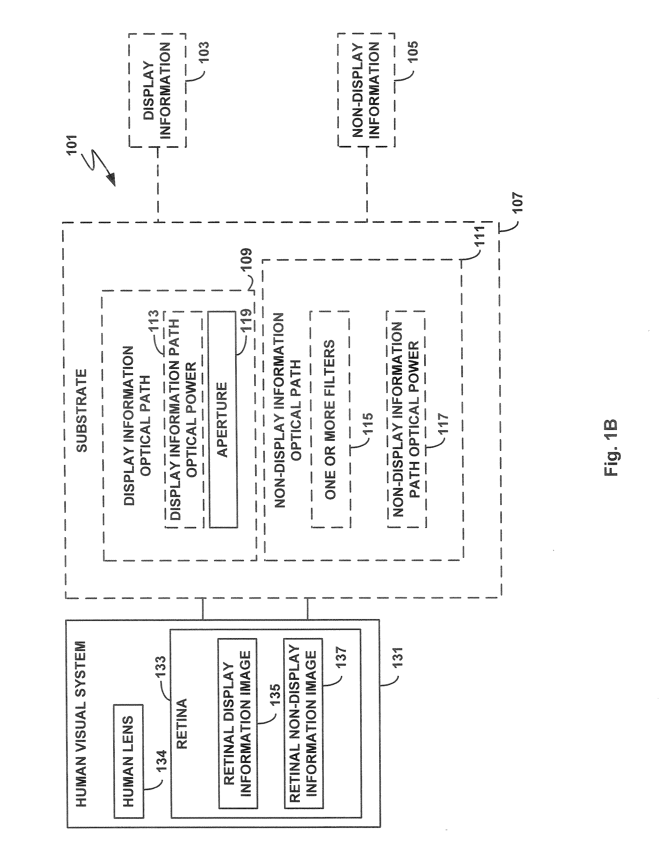
[0007]In a further embodiment, a contact lens assembly is provided, comprising: a curved transparent substrate having at least one patterned filter; and a lenslet attached to the curved transparent substrate. In some such embodiments, the patterned filter is a polarization filter or a patterned spectral filter. In those em...


PUM

PropertyMeasurementUnit
diameteraaaaaaaaaa
diameteraaaaaaaaaa
distanceaaaaaaaaaa

Abstract

Various embodiments of the present invention provide systems, methods, and processes for constructing a contact lens. In one embodiment, a contact lens assembly is provided, comprising: a curved polymer polarizer with an aperture; a lenslet disposed inside the aperture, wherein the lenslet enables imaging near objects; and a filter attached to the lenslet. In further embodiments, a method for fabricating a flexible contact lens is provided, comprising: fabricating an element having an extrusion; providing a front concave mold, wherein the front mold has an intrusion to accommodate the extrusion of the optical element; affixing the extrusion of the optical element to the intrusion of the front mold; attaching a back convex mold to the front concave mold, thereby forming a mold cavity; and filling the mold cavity with a pre-polymerized liquid, whereby upon polymerization, the pre-polymerized liquid forms the flexible contact lens and the optical element is partially encapsulated within the lens.

Description

RELATED APPLICATION[0001]This application is a continuation-in-part of and claims the benefit of U.S. patent application Ser. No. 12 / 204,567 filed Sep. 4, 2008, which is hereby incorporated herein by reference in its entirety.FIELD OF THE INVENTION[0002]The present invention is related to optics and, more specifically, is directed toward the construction of contact lenses having optics used in processing display and non-display optical information.DESCRIPTION OF THE RELATED ART[0003]Current systems for optical processing of display information provided by a head-mounted display and non-display information provided by objects other than the head-mounted display have characteristics that make them unattractive solutions for many applications. The twin requirements of a large field of view and a comfortable eye-to-system distance for the viewer result in multi-component optical systems where the final optical component has a large diameter. Such systems tend to be large, bulky and ill ...

Claims


Application Information

Patent Timeline
Patent Type & Authority Patents(United States)
IPC IPC(8): G02C7/02G02C7/04B29D11/00
CPCB29D11/00048G02C7/104G02B27/0172G02C7/04G02C7/086G02C7/101G02C7/102G02C7/12G02C7/10B29D11/00634G02B5/30G02B2027/0123G02B2027/015G02C2202/04G02C2202/16G02C2202/20B29D11/00038
Inventor LEGERTON, JEROMESPRAGUE, RANDALL
Owner INNOVEGA
Why Eureka
Try Eureka