Rotor blade for use with a wind turbine and method for assembling rotor blade

a technology for wind turbines and rotor blades, which is applied in the direction of liquid fuel engines, vessel construction, marine propulsion, etc., can solve the problems of buckling strength, low rigidity of panel walls, and relatively light panel walls

Active Publication Date: 2012-03-27
LM WIND POWER US TECH APS
View PDF31 Cites 15 Cited by
  • Summary
  • Abstract
  • Description
  • Claims
  • Application Information

AI Technical Summary

Benefits of technology

[0007]The embodiments described herein facilitate assembling a rotor blade that increases an annual energy production of the wind turbine and facilitates reducing the overall costs of manufacturing the rotor blade. More specifically, the rotor blade described herein includes a structural support assembly positioned within a rotor blade cavity that is coupled to a wind turbine hub to facilitate a rotor blade root portion having an airfoil shape at or near the hub of the wind turbine. In addition, by providing a structural support assembly, the rotor blade described herein may be assembled in modular sections, thereby reducing the overall costs of manufacturing the rotor blade.

Problems solved by technology

However, the panel walls are relatively light and have only low rigidity.
Therefore, a stiffness and a rigidity, as well as a buckling strength, of the panel walls may not withstand the loads and forces exerted on the rotor blade during operation.
In at least some known rotor blades, failure of the rotor blades has occurred within the bonded areas of the rotor blade.

Method used


Image

  • Rotor blade for use with a wind turbine and method for assembling rotor blade
  • Rotor blade for use with a wind turbine and method for assembling rotor blade
  • Rotor blade for use with a wind turbine and method for assembling rotor blade

Examples


Embodiment Construction

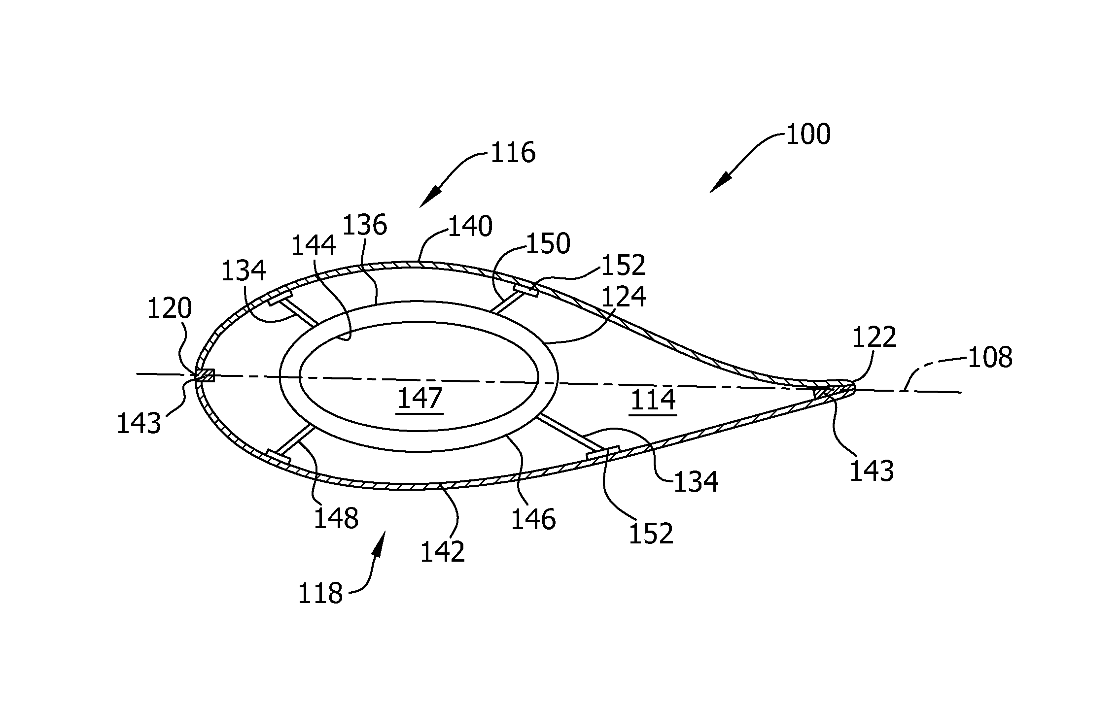
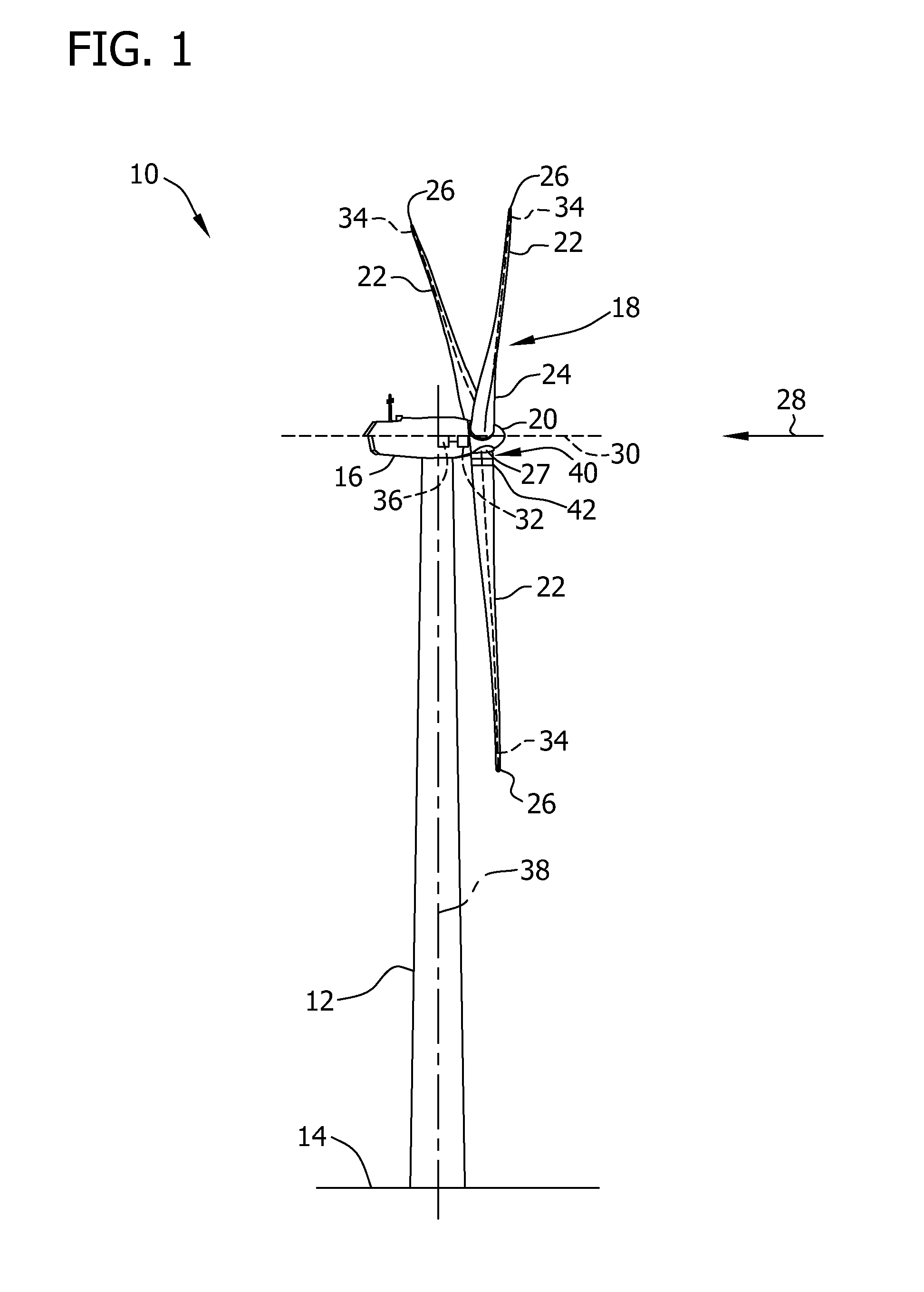
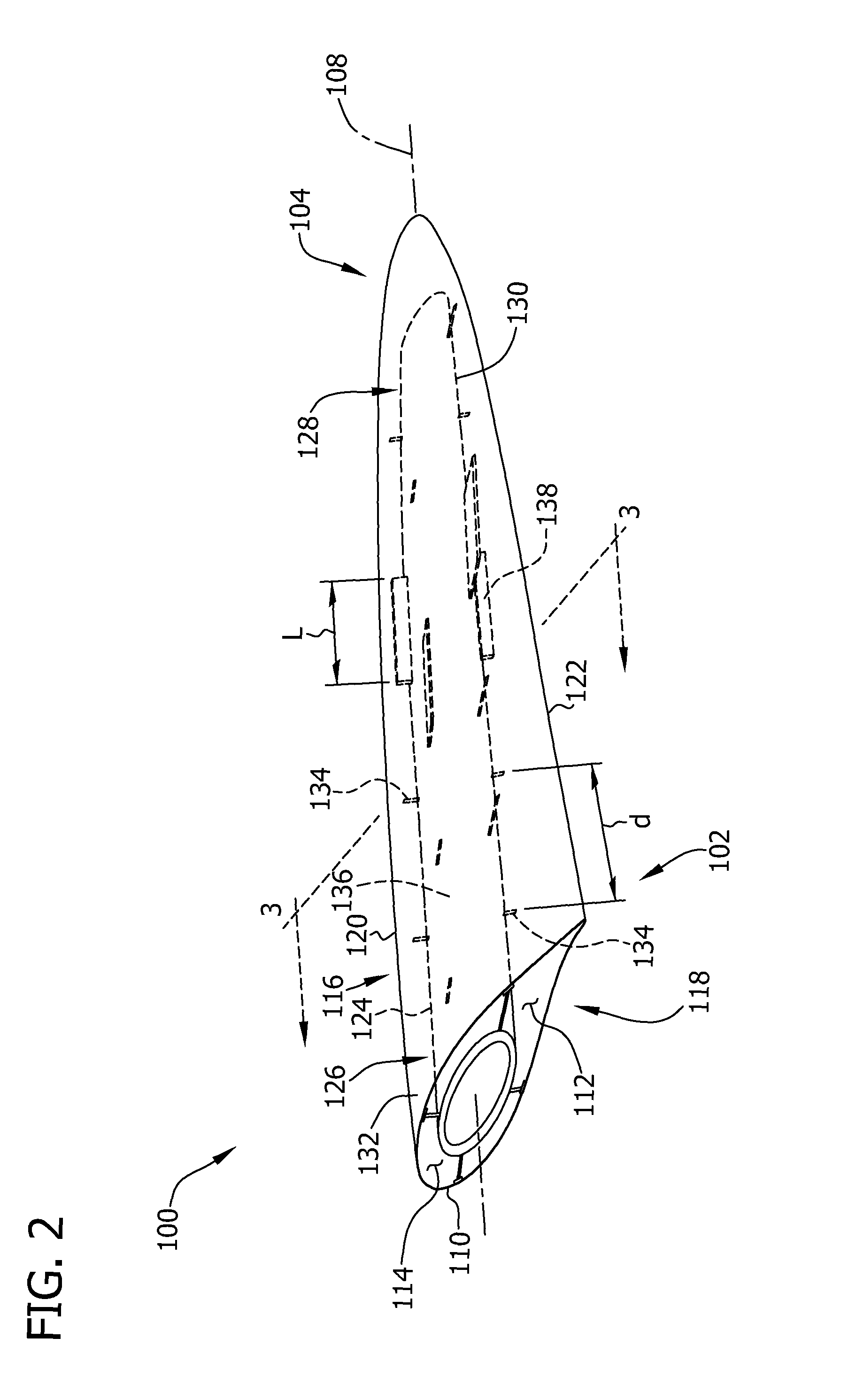
[0014]The embodiments described herein include a wind turbine that includes at least one rotor blade having an airfoil shape along a full length of the rotor blade to facilitate increasing an annual energy production of the wind turbine. More specifically, the rotor blade described herein includes a structural support assembly positioned within a rotor blade cavity that is coupled to a wind turbine pitch bearing to facilitate a rotor blade root portion having an airfoil shape at or near a hub of the wind turbine.

[0015]As used herein, the term “blade” is intended to be representative of any device that provides a reactive force when in motion relative to a surrounding fluid. As used herein, the term “wind turbine” is intended to be representative of any device that generates electrical power from rotational energy, and more specifically, converts kinetic energy of wind into mechanical energy and converts mechanical energy to electrical power. As used herein, the term “annual energy p...


PUM

PropertyMeasurementUnit
lengthaaaaaaaaaa
lengthaaaaaaaaaa
lengthaaaaaaaaaa

Abstract

A method for assembling a rotor blade for use with a wind turbine. The method includes providing a blade sidewall at least partially defining a cavity extending from a blade root towards a blade tip of the rotor blade, the blade sidewall having a leading edge and a trailing edge. A structural support assembly is positioned at least partially within the cavity and extends from the blade root towards the blade tip. The structural support assembly includes a root end and an opposing tip end. At least one support member is coupled to the blade sidewall and to the structural support assembly.

Description

BACKGROUND OF THE INVENTION[0001]The subject matter described herein relates generally to wind turbines and, more particularly, to rotor blades for use with a wind turbine.[0002]At least some known wind turbine rotor blades include two blade shell portions of fiber reinforced polymer. The blade shell portions are molded and then coupled together along cooperating edges using a suitable adhesive material. The blade shell portions typically include panel walls that are made using suitable, evenly distributed fibers, fiber bundles, or mats of fibers layered in a mold part. However, the panel walls are relatively light and have only low rigidity. Therefore, a stiffness and a rigidity, as well as a buckling strength, of the panel walls may not withstand the loads and forces exerted on the rotor blade during operation. To increase the strength of the rotor blade, the blade shell portions are reinforced with sparcaps laminated to the inner surface of the blade shell portions. At least some...

Claims


Application Information

Patent Timeline
Patent Type & Authority Patents(United States)
IPC IPC(8): F03D11/00
CPCF03D1/0641F03D1/0675Y10T29/49337Y02E10/721Y02E10/72
Inventor RAO, KAVALA VENKATESWARASULTAN, MOHAMAD
Owner LM WIND POWER US TECH APS
Why Eureka
Try Eureka