
Power transmission belts

a technology of transmission belts and belts, which is applied in the direction of driving belts, mechanical equipment, ropes and cables for vehicles/pulleys, etc., can solve the problems of power transmission belts on these engines, and achieve the effects of improving the properties of belt growth, wicking, abrasion, and durability

Inactive Publication Date: 2012-03-27
CONTITECH USA INC
View PDF43 Cites 40 Cited by
  • Summary
  • Abstract
  • Description
  • Claims
  • Application Information

AI Technical Summary

Benefits of technology

[0004]The present invention is directed to a power transmission belt. The belt contains therein a compound providing the belt with improved properties in regards to belt growth, wicking, abrasion, and durability.

Problems solved by technology

As a result, power transmission belts on these engines have been required to operate under high load, at high tensions and at high temperatures while reducing belt width.

Method used


Image

  • Power transmission belts
  • Power transmission belts
  • Power transmission belts

Examples


Embodiment Construction

[0015]The following language is of the best presently contemplated mode or modes of carrying out the invention. This description is made for the purpose of illustrating the general principles of the invention and should not be taken in a limiting sense. The scope of the invention is best determined by reference to the appended claims. The reference numerals as depicted in the drawings are the same as those referred to in the specification.

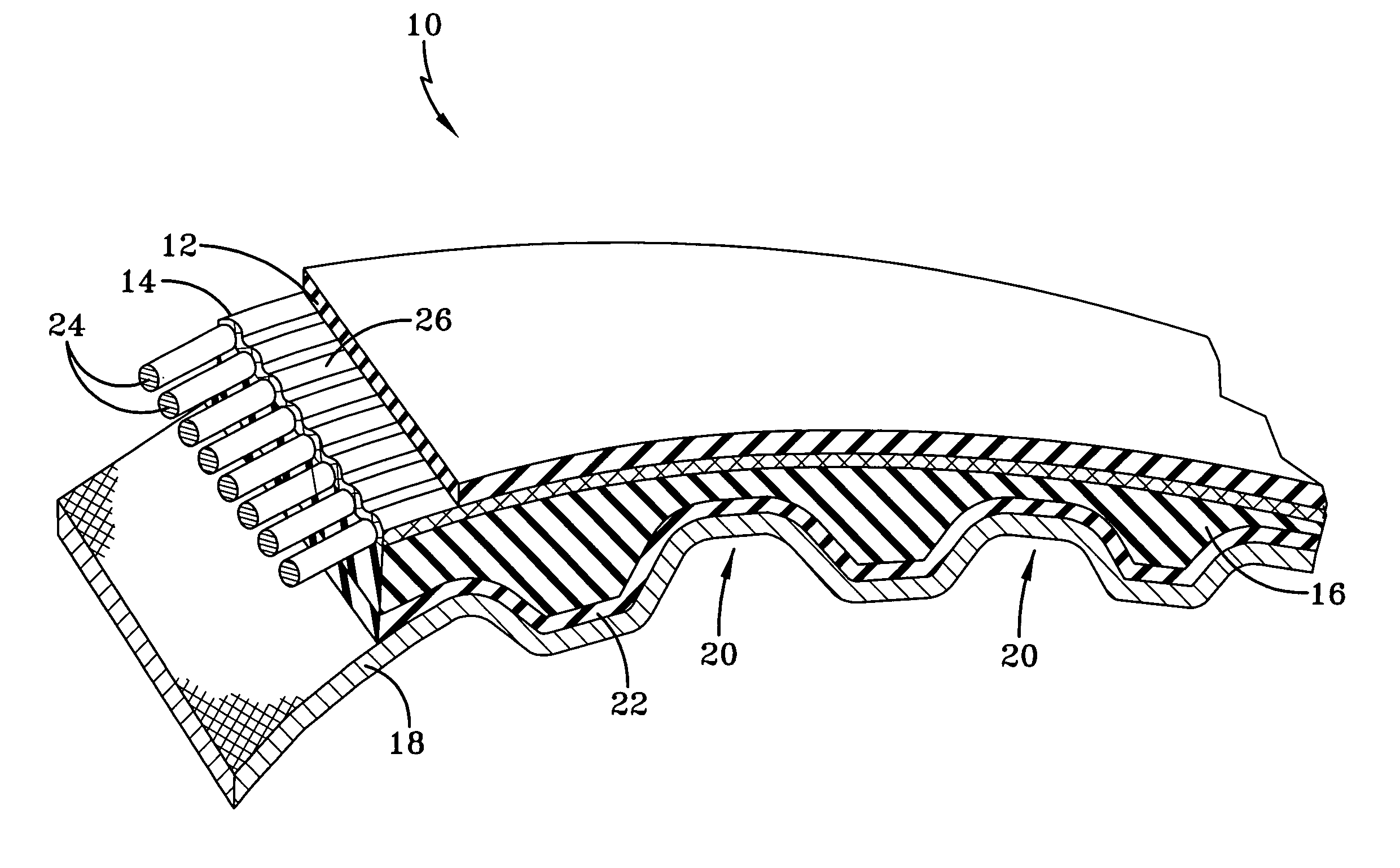
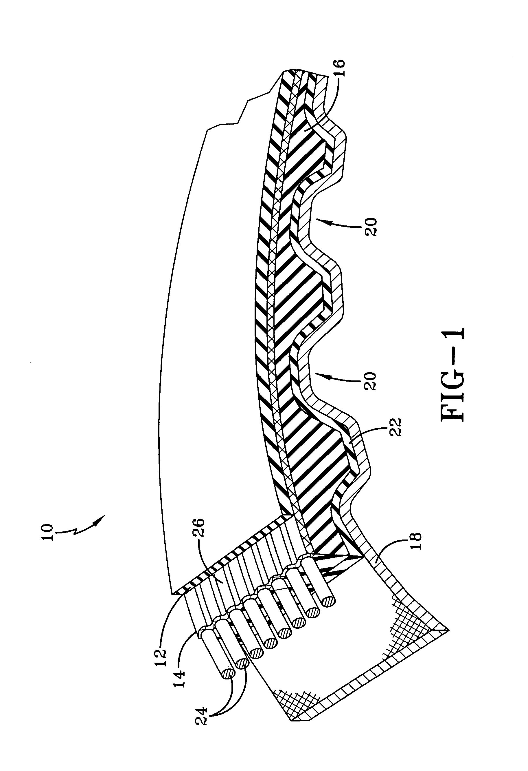
[0016]FIG. 1 illustrates an endless power transmission belt 10. The belt 10 is particularly adapted to be used in associated sheaves in accordance with techniques known in the art. The belt is particularly suited for use in synchronous drive applications. The belt 10 is adapted to be used in so-called torque sensing drives, application where shock loads of varying belt tension are imposed on the belt, applications where the belt is operated at variable speeds, applications where the belt is spring-loaded to control its tension and the like.

[0017]Th...


PUM

PropertyMeasurementUnit
lengthaaaaaaaaaa
thermoplasticaaaaaaaaaa
elastomeric/thermoplasticaaaaaaaaaa

Abstract

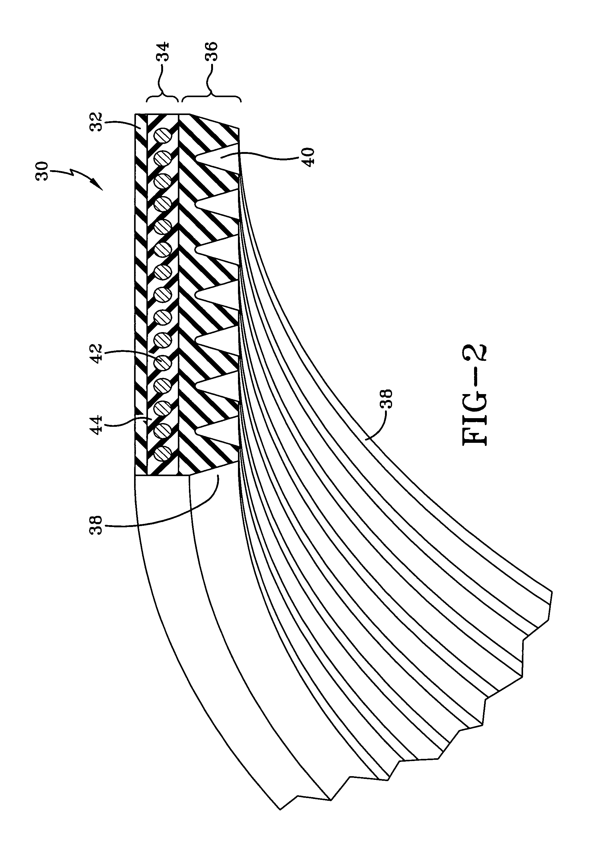
A belt has a compression section, a tension section, and a load carrying section disposed between the compression section and the tension section. The belt has an elastomeric / thermoplastic material, the elastomeric / thermoplastic material has 50 to 90 parts per hundred of an elastomer and 10 to 50 parts per hundred thermoplastic.

Description

FIELD OF THE INVENTION[0001]The present invention is directed to power transmission belts. More specifically, the invention is directed to power transmission belts having improved characteristics achieved by the use of a blended rubber and thermoplastics composition.BACKGROUND OF THE INVENTION[0002]In conventional power transmission belts, the belt has an inner compression section, an outer tension section, and an intermediate neutral plane. Typically, helically wound reinforcing cords are located within the neutral plane and so the neutral plane is also referred to as the load carrying zone. Such belts also having a variety of groove and rib configurations, using longitudinal or transverse grooves or a combination of both. The grooves are located in the inner compression section of the belt. The grooves assist in engaging a pulley in the power transmission system. For some belts, grooves and rib configurations may also be provided in the outer tension section.[0003]Developments in ...

Claims


Application Information

Patent Timeline
Patent Type & Authority Patents(United States)
IPC IPC(8): F16G1/28
CPCF16G1/28F16G5/20
Inventor GOETTSCH, LARRY DEANLOFGREN, JEFFREY DWIGHT
Owner CONTITECH USA INC
Learn More