Multi-gear mechanism for power tools

a multi-gear mechanism and power tool technology, applied in the direction of manufacturing tools, portable power-driven tools, gearing, etc., can solve the problems of high manufacturing cost and complicated structure, and achieve the effect of less complicated, low manufacturing cost and more competitive in the mark

Active Publication Date: 2012-03-27
POWER NETWORK IND
View PDF4 Cites 11 Cited by
  • Summary
  • Abstract
  • Description
  • Claims
  • Application Information

AI Technical Summary

Benefits of technology

[0005]A primary objective of the present invention is to provide a multi-gear mechanism for power tools in which the mechanism includes less complicated structure and can be made at low cost.
[0008]The multi-gear mechanism of the present invention is less complicated when compared with the conventional mechanism and can be manufactured at low cost so that the multi-gear mechanism of the present invention is more competitive in the market.

Problems solved by technology

However, the conventional mechanism involves a complicated structure and high manufacturing cost.

Method used


Image

  • Multi-gear mechanism for power tools
  • Multi-gear mechanism for power tools
  • Multi-gear mechanism for power tools

Examples


Embodiment Construction

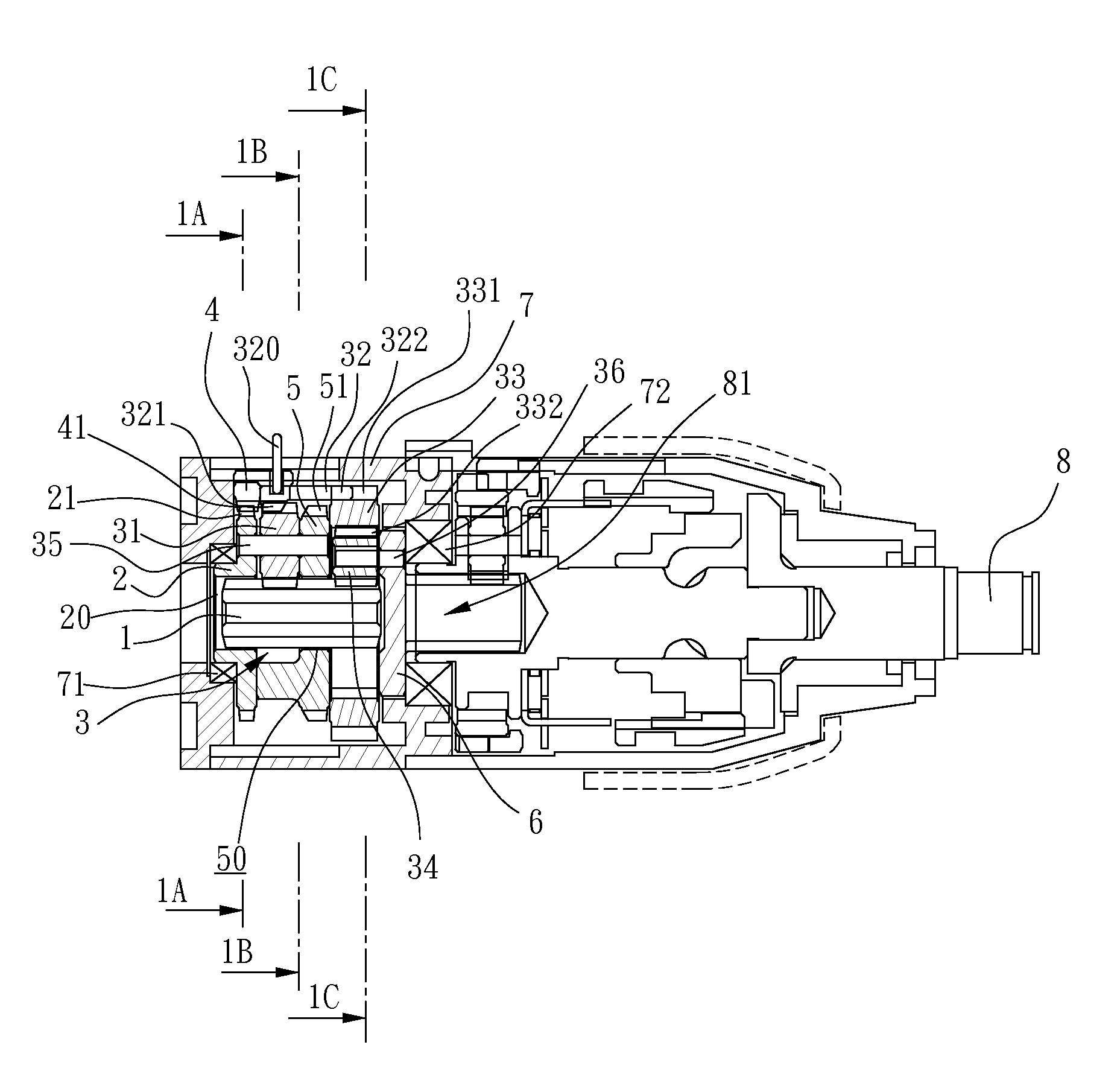
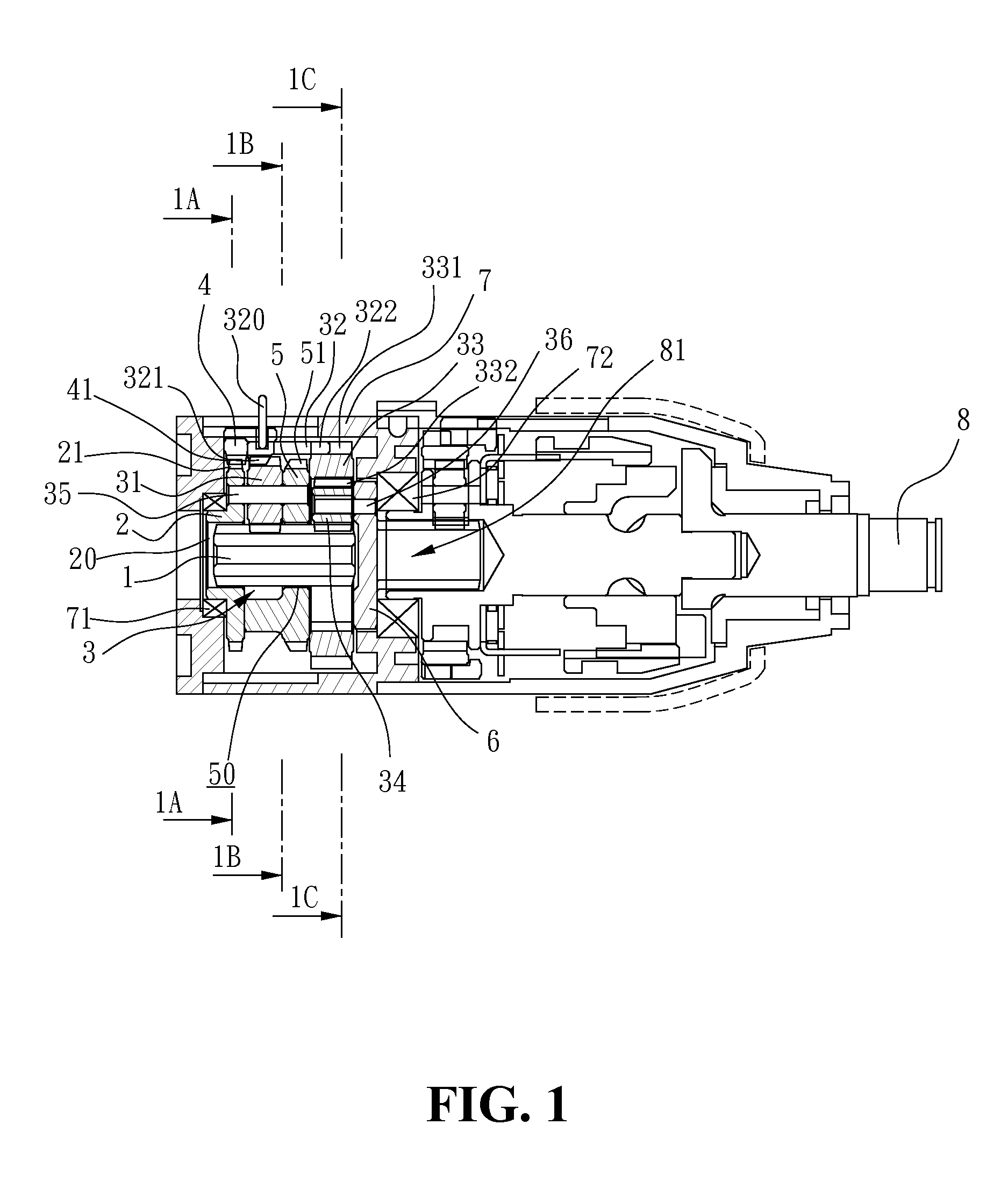
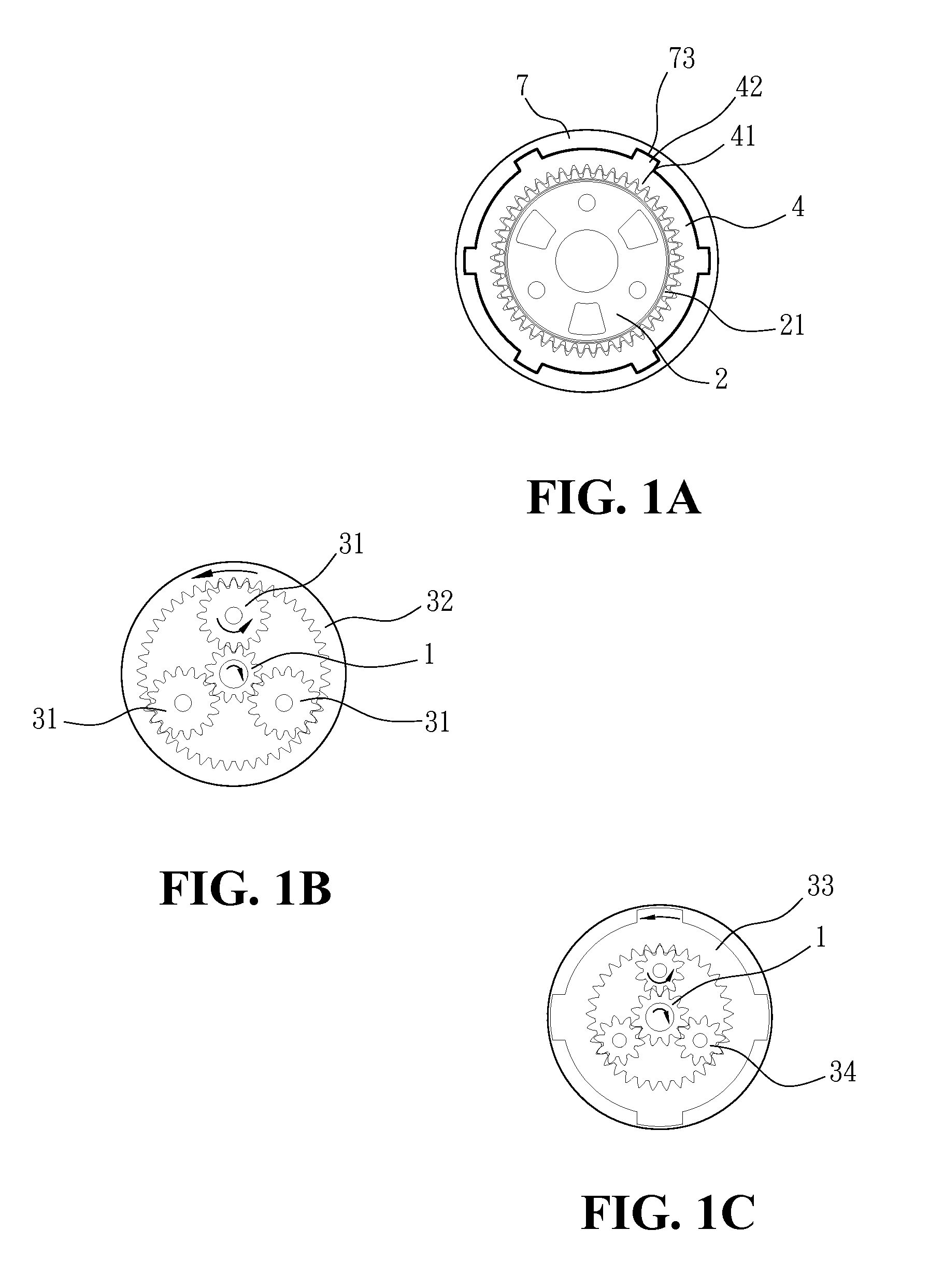
[0022]With reference to the drawings and in particular to FIGS. 1, 1A, 1B and 1C, a multi-gear mechanism for power tools of the present invention comprises a motor gear 1, a first gear set 2 having a first central hole 20 and teeth 21 defined on an outside thereof, an operation gear ring 4, a second gear set 5 having a second central hole 50 and teeth 51 defined on an outside thereof, multiple first planet gears 31 pivotably connected between the first and second gear sets 2, 5 by first pins 35, an output set 6, multiple second planet gears 34 pivotably connected to the output set 6 by second pins 36, a first gear ring 33 including external teeth 331 defined on an outer periphery thereof and internal teeth 332 defined on an inner periphery thereof. The power tool includes an output shaft 8 which can be operated at low speed, constant speed and high speed. The first gear set 2 is cooperated with a first bearing 71 and located within a case 7 of the power tool. The operation gear ring...


PUM


Abstract

A multi-gear mechanism includes first and second gear sets, an output set, multiple first planet gears pivotably connected between the first and second gear sets, a first gear ring having internal teeth and external teeth, multiple second planet gears cooperated with the internal teeth of the first gear ring, a second gear ring having internal teeth and side teeth, an operation gear ring and a motor gear. The motor gear extends through two central holes of the first and second gear sets, and the first and second planet gears are engaged with the motor gear. The operation gear ring is connected with the second gear ring which drives the operation gear ring to move axially. The motor gear drives the output set at low speed, constant speed or high speed when the operation gear ring and the second gear ring are operated to engage with different gears.

Description

BACKGROUND OF THE INVENTION[0001]1. Field of the Invention[0002]The present invention relates generally to a multi-gear mechanism for power tools, and in particular to a mechanism for adjusting speed of the power tools.[0003]2. The Prior Arts[0004]Conventional power tools use a gear set to adjust the speed of the motor in the power tool so as to obtain desired speed on the output shaft. The conventional mechanism for adjustment of the speed of the output shaft generally provides three modes which are low speed, constant speed and high speed. However, the conventional mechanism involves a complicated structure and high manufacturing cost.SUMMARY OF THE INVENTION[0005]A primary objective of the present invention is to provide a multi-gear mechanism for power tools in which the mechanism includes less complicated structure and can be made at low cost.[0006]The mechanism includes a lever which extends out from a case of a power tool and users can shift the lever axially to control the m...

Claims


Application Information

Patent Timeline
Patent Type & Authority Patents(United States)
IPC IPC(8): F16H3/44B25D16/00
CPCB25F5/001F16H3/66F16H2200/0039F16H2200/2064
Inventor CHEN, TING-KUANG
Owner POWER NETWORK IND
Why Eureka
Try Eureka