
Directional control system and method for marine vessels, such as ships and the like

a directional control system and marine technology, applied in the direction of position/direction control, steering components, floating buildings, etc., can solve the problems of secondary steerage stations, complex addition of additional components, and directional control systems in the prior, so as to achieve the effect of high cost, reduced cost, and more complex tasks

Active Publication Date: 2005-11-17
ULTRAFLEX
View PDF1 Cites 14 Cited by
  • Summary
  • Abstract
  • Description
  • Claims
  • Application Information

AI Technical Summary

Benefits of technology

[0016] Briefly, a directional control system for a marine vessel is provided that comprises a steering mechanism movable between two extreme opposite positions and capable of altering the direction of the marine vessel; an actuator for moving the steering mechanism between the two extreme opposite stop positions; a directional control station comprising a control element movable between two opposite positions to set a directional steering; and an electrical transmission system transmitting to the actuator the movement stroke of the control element or the position of the control element in the total stroke between the two opposite positions. The electrical transmission system transforms the movement stroke of the control element, or the position of the control element, into an actuation signal for the actuator according to a function univocally correlated with the position of the steering mechanism, thereby causing the steering mechanism to assume a steering position that directly corresponds to the actuation signal.
[0057] In a different embodiment, it is possible to perform more complex tasks with lower costs by the use of a less complex hardware structure. In this embodiment, the intelligent processing unit associated to the transducer is removed and a different type of electro-mechanical transducer is used to transform the movement of the control element into a directional steering. More specifically, the detection of the stroke or position of the control element to set the directional steering comprises the use of an opto-electronic transducer.

Problems solved by technology

Yet the directional control systems in the prior art present a number of drawbacks.
A first drawback is that the assembly of purely mechanical and hydraulic systems requires the passage of pull and push cables or of hydraulic piping running through the ship vessel or parts thereof.
Another drawback is the complexity of adding additional, secondary steerage stations, because the mechanical and hydraulic integration of cables and pipes connected to the secondary stations with the cables and pipes already in place is extremely difficult or even impossible without substantial changes to the stations already in place.
Still another drawback is the need to adjust only with mechanical or hydraulic means the function that correlates the position of the steering control element with the corresponding position of the dipped steering mechanism, for instance, the function correlating the angular position of the steering wheel with the angular position of a rudder blade or sterndrive of an outboard motor, only with mechanical or hydraulic means, because the steering control element and the dipped steering mechanism are integrated with a mechanical system (cables and tie rods) or a hydraulic system (connections of fluid piping and possible distribution).
Such adjustments must be frequently carried out, since both mechanical systems and hydraulic systems are subject to a degradation in their operating conditions, for instance, to an increase in slacks, a decrease in the amount of fluid, or other wear-related effects.
In this situation, a system examination must be carried out for in the entire mechanical or hydraulic system, since cables may broken at any point, and fluid pipes may leak or be broken in different points.
Yet another drawback is the inherent lack of flexibility of the functions correlating the position of the control element with the position of the steering mechanism in the prior art, which prevents these functions from being changed or modified, and also make it problematic to execute or integrate diagnostic and emergency systems and functionalities.
A further drawback is the difficulty in integrating the steerage systems in the prior art within an electronic function control system, for instance, for accelerating or reversing control.

Method used


Image

  • Directional control system and method for marine vessels, such as ships and the like
  • Directional control system and method for marine vessels, such as ships and the like
  • Directional control system and method for marine vessels, such as ships and the like

Examples


first embodiment

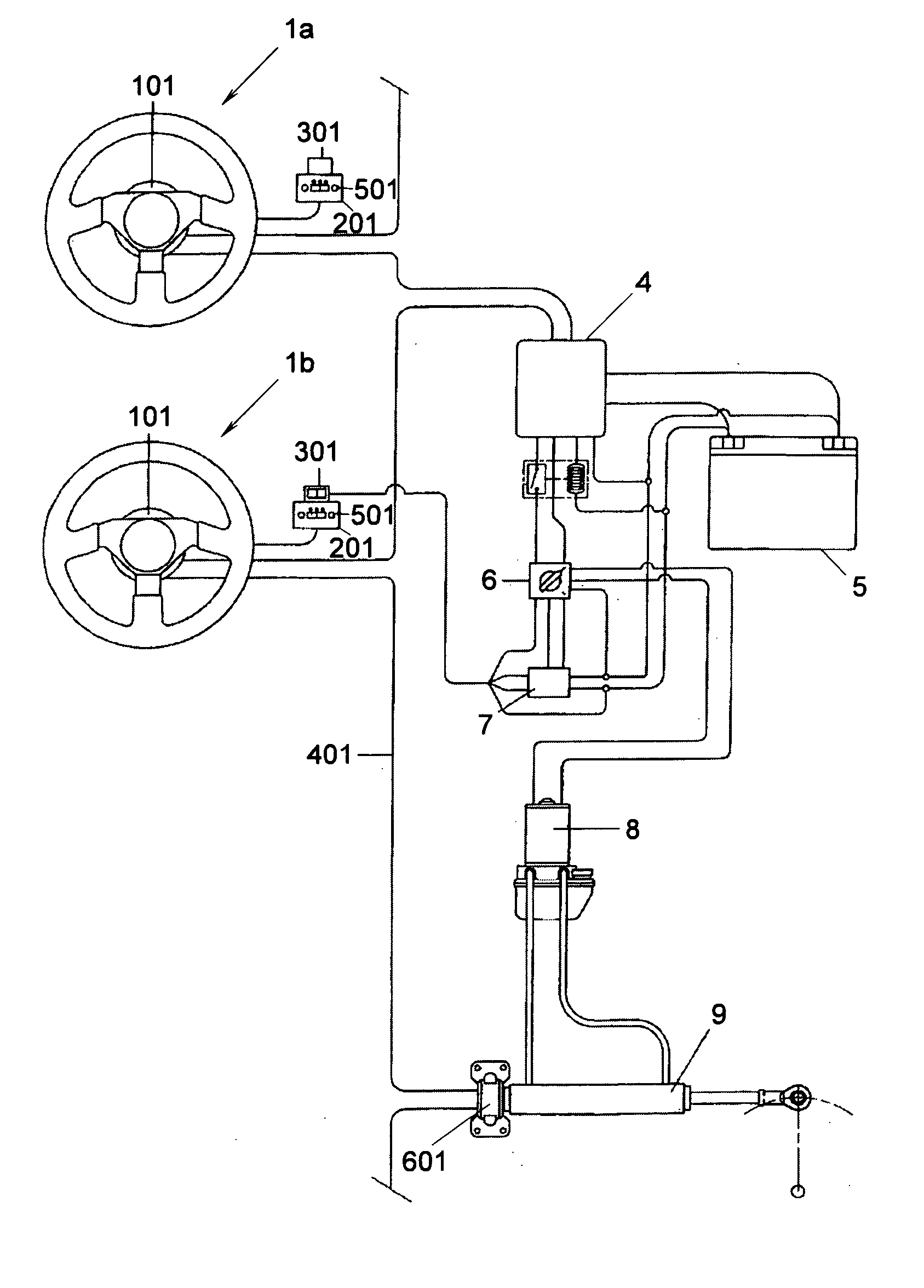
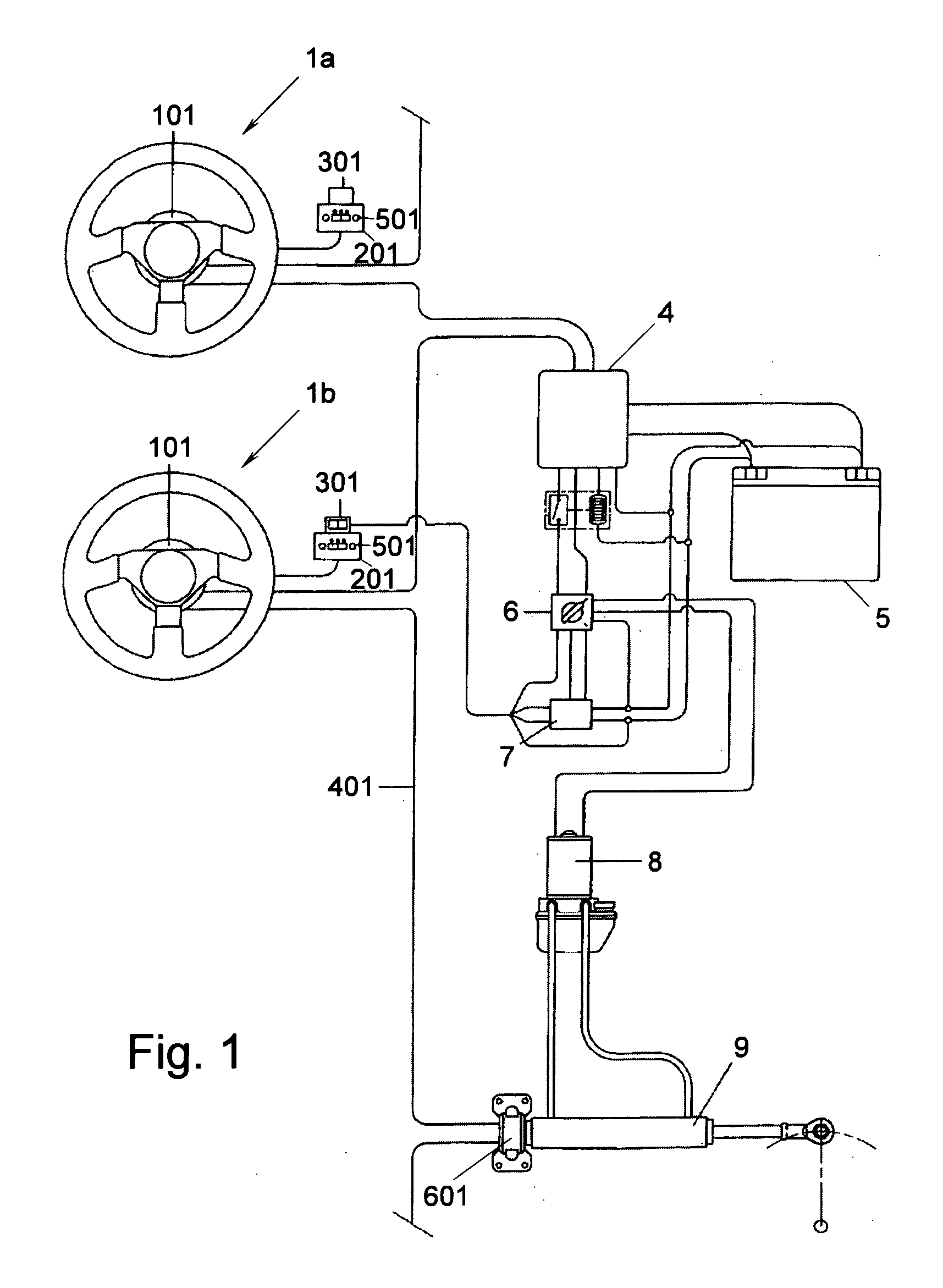
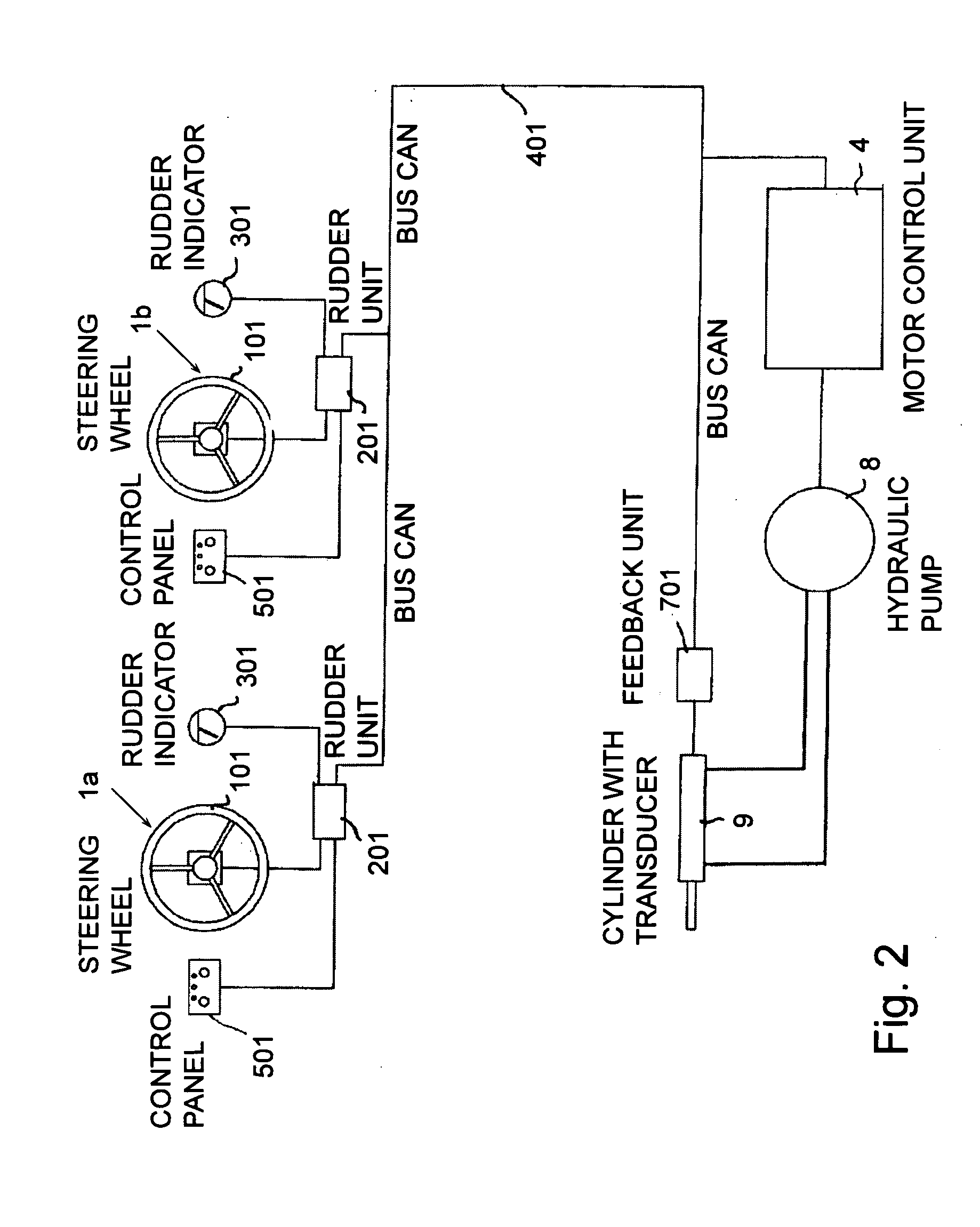
[0080] Means for inputting data or commands, shown in the first embodiment as a control panel 501, are also connected to one input point of rudder unit 201.

[0081] A control and processing unit 4 is connected to the device that actuates the steering mechanism and comprises a control unit that regulates the power supply to an electric motor driving a hydraulic pump 8. Such hydraulic pump is part of a closed hydraulic circuit that supplies a double-acting hydraulic actuating cylinder 9. Control and processing unit 4 may have a structure similar to rudder unit 201, and may comprise a feedback unit connected to hydraulic cylinder 9 which generates and transmits on communication line 401 a signal indicating the actual angular position of the steering mechanism. Such feedback unit preferably comprises a sensor that detects the position or stroke made by hydraulic actuating cylinder 9 and that provides a signal to a control and processing unit 601. The latter generates the feedback signal c...

second embodiment

[0179]FIGS. 5 and 6 show an electro-hydraulic steerage according to the present invention.

[0180] The second embodiment may comprise a single control station, as shown in FIG. 5, or two control stations as shown in FIG. 6. Contrary to the first embodiment, the directional control element, that is, the steering wheel 101 connected to the rudder, is provided in combination with an angular position sensor, preferably an encoder 30. Such encoder 30 is composed of an optical movement sensor able to generate a pulse every 2 degrees of rotation and of a digital direction discriminator.

[0181] As can be seen in FIG. 7, the encoder comprises a shielding disk 130 that is mounted coaxially to the steering wheel 101 and that can be rotate with said steering wheel 101. Along a predetermined circumference, the shielding disk 130 has a row of through slots 230 having the same shape and span. Slots 230 have the same angular width and are alternated with full areas having the same angular width.

[018...


PUM


Abstract

A directional control system for a marine vessel comprising a steering mechanism movable between two extreme opposite positions and capable of altering the direction of the marine vessel; an actuator for moving the steering mechanism between the two extreme opposite stop positions; a directional control station comprising a control element movable between two opposite positions to set a directional steering; and an electrical transmission system transmitting to the actuator the movement stroke of the control element or the position of the control element in the total stroke between the two opposite stop positions. The electrical transmission system transforms the movement stroke of the control element, or the position of the control element, into an actuation signal for the actuator according to a function univocally correlated with the position of the steering mechanism, thereby causing the steering mechanism to assume a steering position that directly corresponds to the actuation signal.

Description

CROSS-REFERENCE TO RELATED APPLICATIONS [0001] The present patent application claims priority under 35 U.S.C. § 119 to Italian patent application SV2004A000023, filed on May 17, 2004. STATEMENT REGARDING FEDERALLY SPONSORED REASEARCH AND DEVELOPMENT [0002] Not applicable. REFERENCE TO A COMPUTER LISTING, A TABLE, OR A COMPUTER PROGRAM LISTING COMPACT DISK APPENDIX [0003] Not applicable. BACKGROUND OF THE INVENTION [0004] 1. Field of the Invention [0005] The present invention relates to a directional control system for a marine vessel, and, more particularly, to a directional control system wherein a stroke of the control element, for example, of the steering wheel, or a position of the control element with respect to the total stroke, is transmitted electrically to a steering device, such as a rudder. [0006] 2. Description of Related Art [0007] Directional control systems in the prior art are known as steerage systems, and generally comprise a control element, such as a steering whe...

Claims


Application Information

Patent Timeline
IPC IPC(8): B63H25/02
CPCB63H25/02
Inventor GAI, GIORGIO
Owner ULTRAFLEX
Learn More