Steam turbine plant

a steam turbine and plant technology, applied in the direction of machines/engines, water feed control, lighting and heating apparatus, etc., can solve the problems of large internal structure, large space of the steam condenser neck, and difficulty in planning such so as to reduce the cost of a steam turbine plant construction and improve the space efficiency inside the steam condenser

Inactive Publication Date: 2006-04-25
KK TOSHIBA
View PDF6 Cites 13 Cited by
  • Summary
  • Abstract
  • Description
  • Claims
  • Application Information

AI Technical Summary

Benefits of technology

[0014]In accordance with the aspect of the present invention, feedwater heating lines provided inside of the steam condensers are reduced so that space efficiency inside the steam condensers are improved and that the costs for a construction of the steam turbine plant are also reduced.

Problems solved by technology

Nevertheless, since each of the low pressure feedwater heaters are connected with the bleeding lines, which extend from the casings of the low pressure turbines as a heating source, space of the neck portion of the steam condensers is relatively small.
This causes difficulty in planning such a steam turbine plant, especially in designing an arrangement of bleeding lines, feedwater heating lines or supports of these bleeding lines or low pressure feedwater heater at the neck portions.
And it may result in necessity of further internal structure inside the steam condensers.
This may cause necessity of enlarging space for the plant itself.
And it may cause not only increase of costs but also pressure drop of the steam flowing inside of the steam condensers, which may effects reduction of the plant efficiency.
However, in order to avoid unbalance of the feedwater among the feedwater heating lines, it is desirable to provide less numbers of feedwater heating lines, which may contribute to increasing redundancies of controls of the steam turbine plant, especially for nuclear power plant.

Method used


Image

  • Steam turbine plant
  • Steam turbine plant
  • Steam turbine plant

Examples


first embodiment

[0020 in accordance with the present invention will be explained with reference to FIG. 1 to FIG. 14.

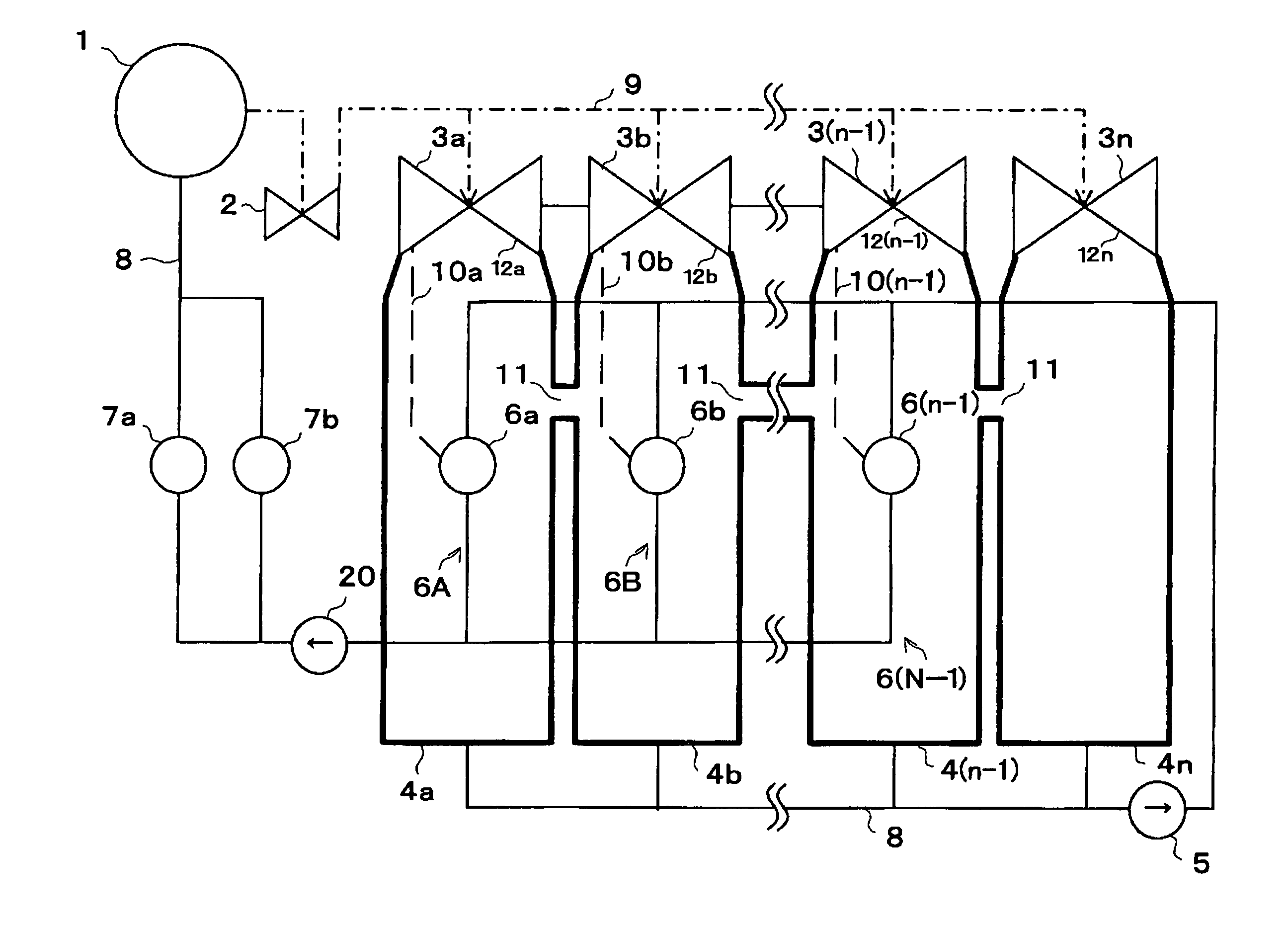
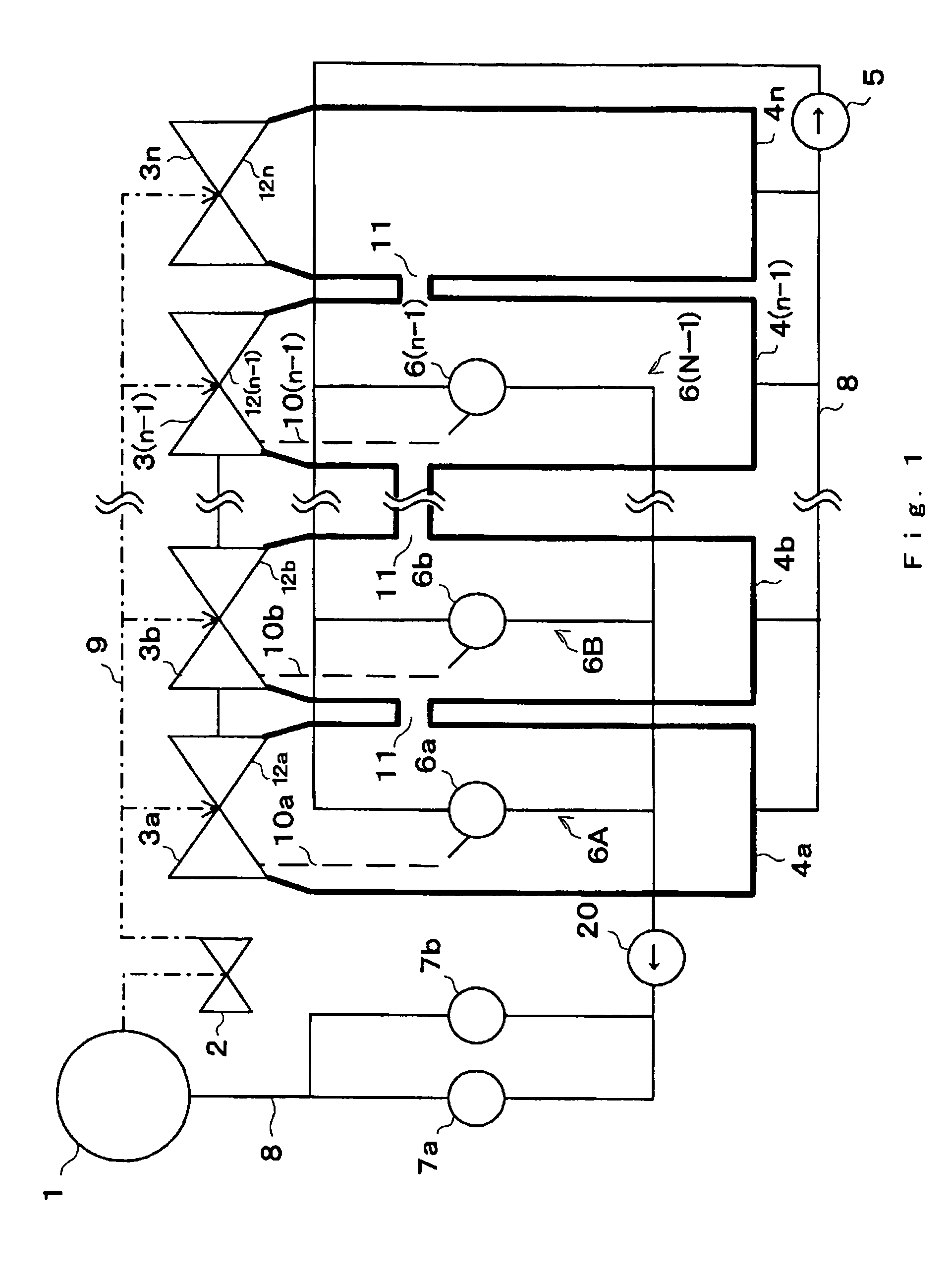
[0021]FIG. 1 is a schematic diagram of a steam turbine plant in accordance with the present invention, which includes n units of low pressure turbines, n units of casings, and n units of steam condensers.

[0022]Steam generator 1, which is connected with a heating source (not shown), for example nuclear reactor or boiler, generates steam. The steam passes through high pressure turbine 2 and steam line 9, then lead to a plurality of casings 12a, 12b, 12c, . . . and 12n of low pressure turbines 3a, 3b, 3c, . . . and 3n. Generally, the number of low pressure turbines 3a, 3b, 3c, . . . and 3n are more than or equal to three (3). Each of low pressure turbines 3a, 3b, 3c, . . . and 3n are installed in casings 12a, 12b, 12c, . . . and 12n, whose number is also the same as the number of low pressure turbines 3a, 3b, 3c, . . . and 3n. The steam led to each of the casings 12a, 12b, 12c, . . . an...

second embodiment

[0066 in accordance with the present invention will be explained with reference to FIG. 13 to FIG. 15.

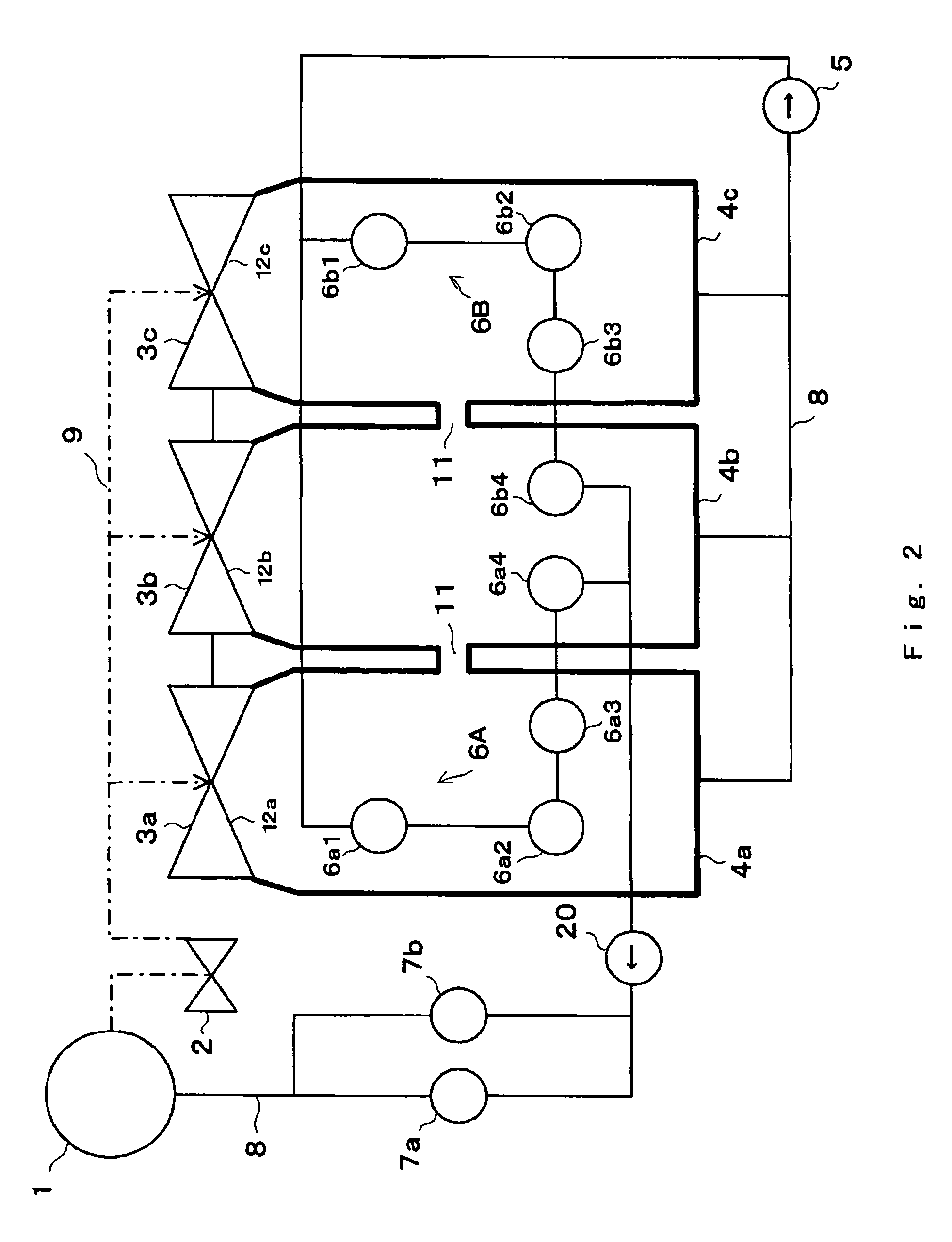
[0067]FIG. 14 is a schematic diagram of a steam turbine plant in accordance with the present invention, which includes n units of low pressure turbines, n units of casings, and n units of steam condensers.

[0068]As is the same manner with the first embodiment shown in FIG. 1, steam generator 1 generates steam. The steam passes through high pressure turbine 2 and steam line 9, then lead to a plurality of casings 12a, 12b, 12c, . . . and 12n of low pressure turbines 3a, 3b, 3c, . . . and 3n. Each of low pressure turbines 3a, 3b, 3c, . . . and 3n are installed in casings 12a, 12b, 12c, . . . and 12n, whose number is also the same as the number of low pressure turbines 3a, 3b, 3c, . . . and 3n. The steam led to each of the casings 12a, 12b, 12c, . . . and 12n drives each of low pressure turbines 3a, 3b, 3c, . . . and 3n. The steam is then discharged from low pressure turbines 3a, 3b, 3c,...


PUM


Abstract

Steam turbine plant includes a steam generator, a plurality of low pressure turbines being driven by steam from the steam generator, a plurality of steam condensers to condense the steam from the low pressure turbines into condensed water and a feedwater line which supplies the condensed water to the steam generator as feedwater. The feedwater line including a plurality of feedwater heating lines connected in parallel. A number of feedwater heating lines being less than a number of steam condensers. Each of the feedwater heating lines includes at least one low pressure feedwater heater provided in at least one of the steam condensers to heat the condensed water by steam bled from the low pressure turbines.

Description

CROSS REFERENCE TO RERATED APPLICATION[0001]This application is based upon and claims the benefit of priority from the prior Japanese Patent Application No. 2003-63723 filed on Mar. 10, 2003;the entire contents of which are incorporated herein by reference.FIELD OF THE INVENTION[0002]The present invention relates to steam turbine plant.[0003]More specifically, the invention relates to steam turbine plant for power generation, which is provided with a feedwater heater in a steam condenser.DESCRIPTION OF THE BACKGROUND[0004]A steam turbine plant includes steam generator, high pressure turbine, a plurality of low pressure turbines. The steam turbine plant further includes a plurality of steam condensers which condense steam from the plurality of low pressure turbines and a plurality of low pressure feedwater heaters which are provided within the steam condensers as the structural elements respectively. A feedwater heater which is provided within a steam condenser is also called as a ne...

Claims


Application Information

Patent Timeline
Patent Type & Authority Patents(United States)
IPC IPC(8): F01K1/00F01K25/08F01K7/34F01K9/02F22D1/32F22D5/18G21D5/02F22D1/34F01K7/42F01K9/00F22D11/00
CPCF01K7/42F22D1/325F01K9/00
Inventor KUMAGAI, KENJISAWA, YUKIHIKOWATANABE, KOICHI
Owner KK TOSHIBA
Why Eureka
Try Eureka