
Electric motor having electrical connecting elements for connection to winding leads

a technology of winding leads and electrical connections, applied in the field of electric motors, can solve the problems of requiring a great deal of manual work, and achieve the effects of low contact resistance values, and easy connection

Active Publication Date: 2012-03-27
EBM PAPST ST GEORGEN & -
View PDF19 Cites 16 Cited by
  • Summary
  • Abstract
  • Description
  • Claims
  • Application Information

AI Technical Summary

Benefits of technology

[0007]In accordance therewith, the winding ends of the individual windings can easily be connected to the mounting elements of the associated connecting elements, for example by resistance welding, with the result that low contact resistance values are obtained. The connecting elements can in turn be electrically connected in the desired fashion by means of a functionally appropriate connecting arrangement in order to obtain, for example, a Y double-parallel circuit or a delta quadruple-parallel circuit. A connecting arrangement of this kind can be implemented as a connecting board having electrical conductors, each of which is connected to specific associated connecting elements by means of contact elements such as, for example, press-in pins or contact pins, so that low contact resistance values are obtained here as well. These press-in pins can quickly and easily be pressed into corresponding press-in seats in the connecting board.
[0008]The invention thus enables rapid, uncomplicated, and highly automated production of high-quality stators that can be used at high ambient temperatures and / or high current intensities and / or in a context of severe vibration stress. One preferred application is motors for low operating voltages such as those that must be used for safety reasons in mining, where such motors are subject to particularly severe vibration stress and at the same time a high level of operating reliability is demanded.

Problems solved by technology

This requires a great deal of manual work.

Method used


Image

  • Electric motor having electrical connecting elements for connection to winding leads
  • Electric motor having electrical connecting elements for connection to winding leads
  • Electric motor having electrical connecting elements for connection to winding leads

Examples


Embodiment Construction

[0026]In the description that follows, the terms “left,”“right,”“upper,” and “lower” refer to the respective figure of the drawings, and can vary from one figure to the next as a function of a particular orientation (portrait or landscape) that is selected. Identical or identically functioning parts are labeled with the same reference characters in the various figures, and usually are described only once.

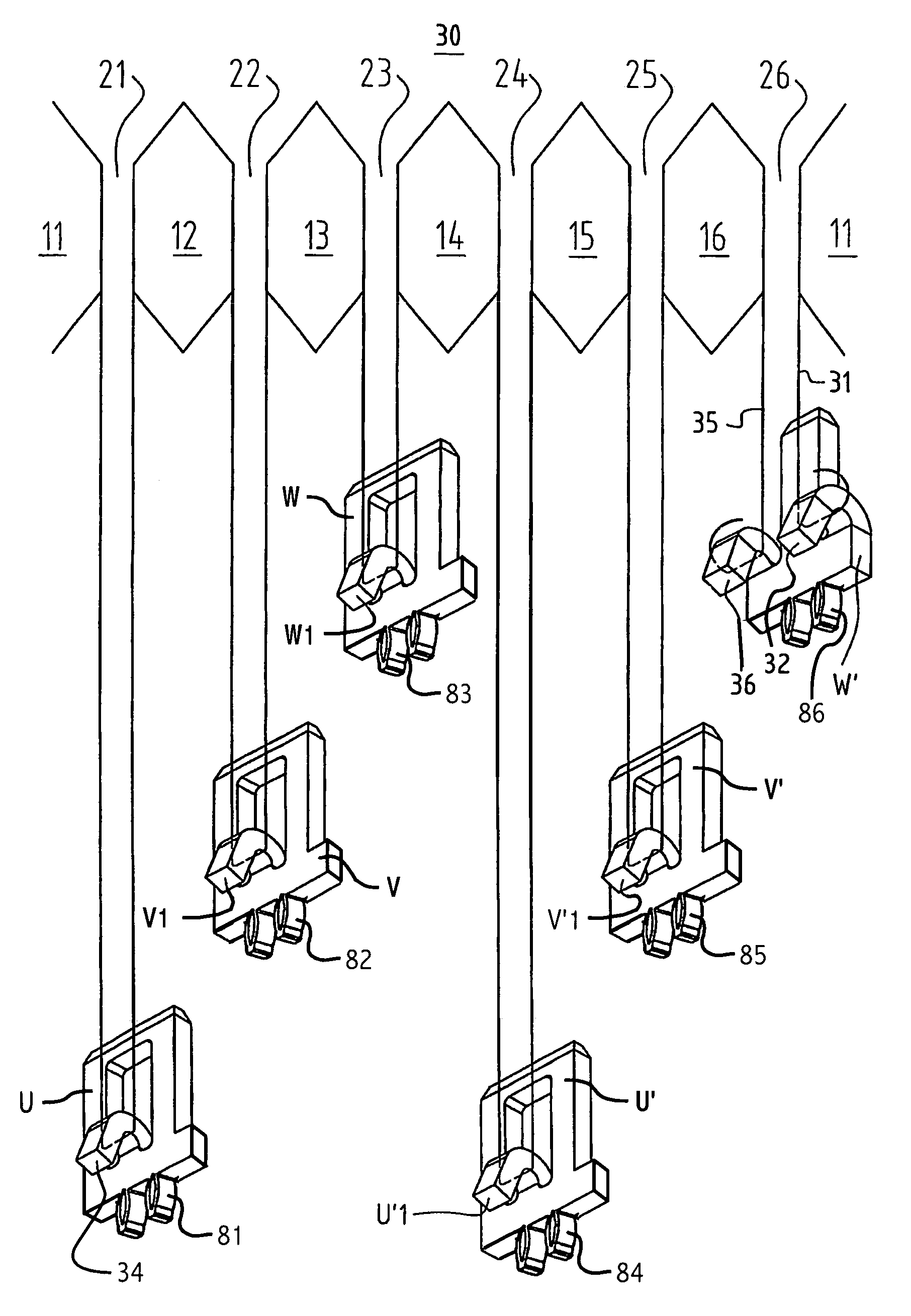
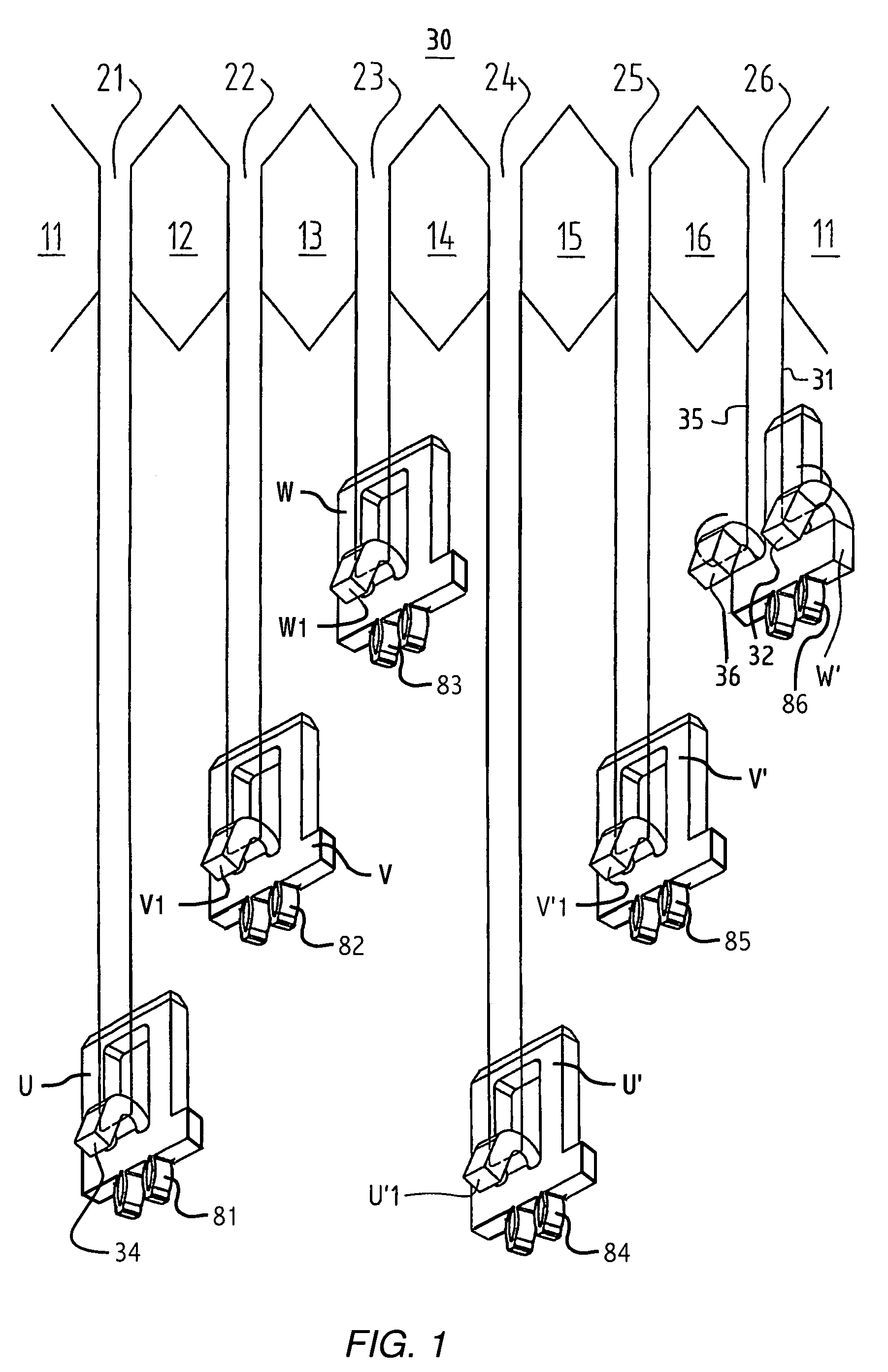
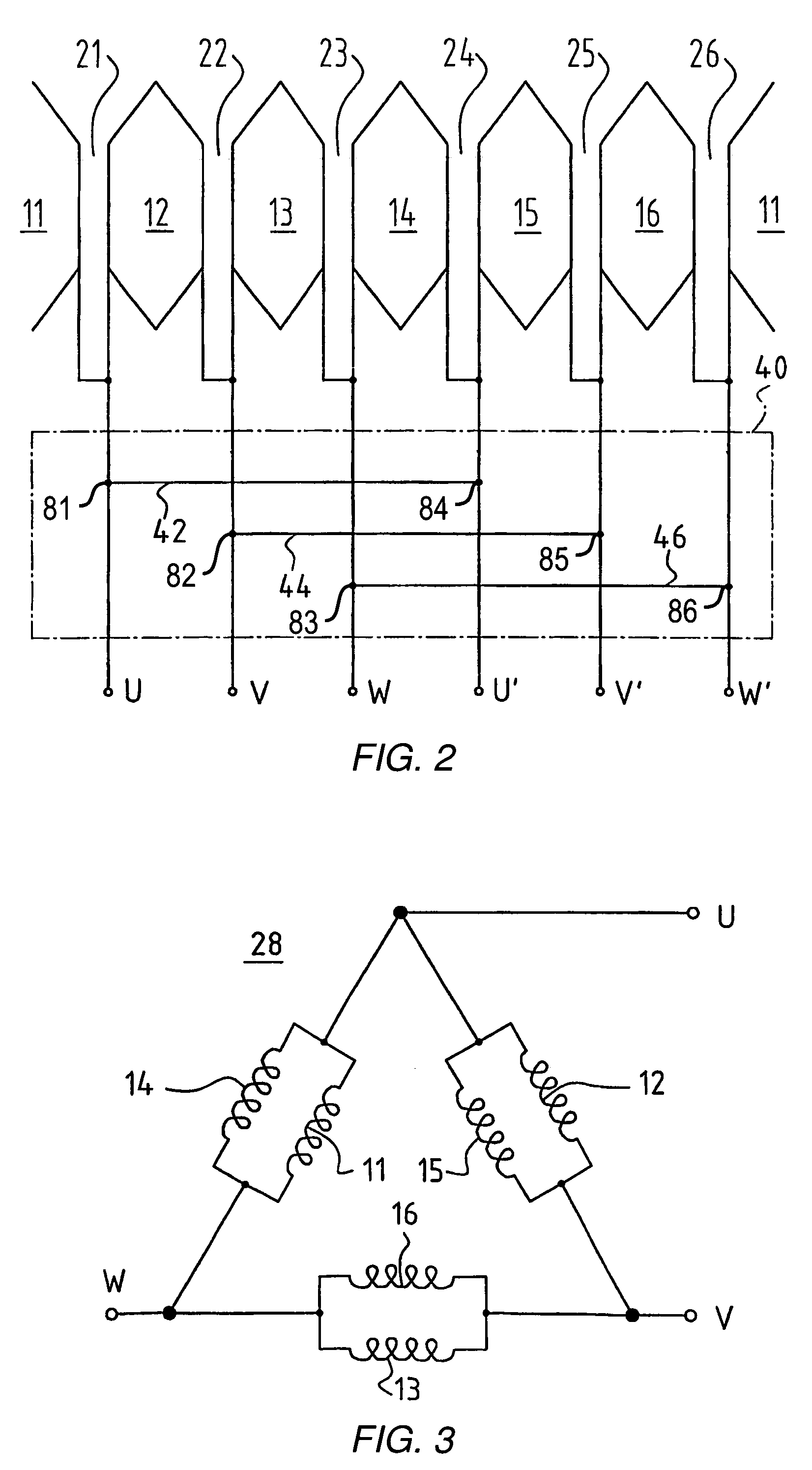
[0027]FIGS. 1 to 4 show a first exemplifying embodiment of the invention, namely a motor having six salient stator poles 11′ to 16′ onto which six coils 11 to 16 are wound continuously and codirectionally. The slot between poles 11′ and 12′ is labeled 21, the slot between poles 12′ and 13′ is labeled 22, and so on for slots 23 to 26.

[0028]This continuous winding 30 is intended for a delta double-parallel circuit 28 as depicted in the usual way in FIG. 3.

[0029]According to FIG. 1, the continuous winding 30 starts at its beginning 31 at hook 32 of an electrical connecting element W′, ...


PUM


Abstract

An electric motor has a rotor (52) and a stator (60) equipped with salient poles on each of which is provided a winding (88 to 99), which windings together form a winding arrangement (85′), electrical connecting leads (88′ to 99′) being provided between at least some of the windings. The stator (60) further has electrical connecting elements (108 to 119) that are arranged on at least one insulating carrier (102) and are equipped with contact elements (108″ to 119″) and with mounting elements (108″″ to 119″″), which latter serve for electrical and mechanical connection to the connecting leads (88′ to 99′). The use of a printed circuit board (140) formed with press-fit seats, to receive the contact elements, facilitates rapid, secure and automated connection of stator windings to other circuit parts, which is particularly useful in making low-voltage, high-current motors such as those used in mining.

Description

CROSS-REFERENCE[0001]This application is a sec. 371 of PCT / EP07 / 08792, filed 10 Oct. 2007 and published 17 Apr. 2008 as WO 2008-43534-A1, which claims priority from DE 20 2006 016 357.3, filed 14 Oct. 2006, the entire content of which is incorporated by reference.FIELD OF THE INVENTION[0002]The invention relates to an electric motor having a stator that carries a winding arrangement that is configured to generate a rotating field.BACKGROUND[0003]A three-phase motor (rotary current motor) can be operated in a Y circuit configuration (Y configuration) and in a delta configuration. If, in the context of a Y circuit, the individual windings of each phase are connected in series, this is referred to as a “Y series” circuit; and if two individual windings per phase are connected in parallel, this is referred to as a “Y double-parallel” circuit, If four individual windings are connected in parallel, the term used is a “Y quadruple-parallel” circuit. Analogously, the terms “delta series” ci...

Claims


Application Information

Patent Timeline
Patent Type & Authority Patents(United States)
IPC IPC(8): H02K11/00H01R12/53H01R12/51H02K15/085H01R12/55
CPCH02K3/522
Inventor ALTINDIS, ISMAIL
Owner EBM PAPST ST GEORGEN & -
Learn More