Micro-electromechanical system based switching

a micro-electromechanical and switching technology, applied in the field of switching devices, can solve the problems of mechanically overloaded equipment, short circuit faults, high impedance paths, etc., and achieve the effect of facilitating the interruption of an electrical curren

Active Publication Date: 2012-03-27
ABB (SCHWEIZ) AG
View PDF55 Cites 22 Cited by
  • Summary
  • Abstract
  • Description
  • Claims
  • Application Information

AI Technical Summary

Benefits of technology

[0015]Another embodiment of the invention includes a method of controlling an electrical current passing through a current path having a set of conduction interfaces with geometry of a defined fuse terminal geometry. The method includes measuring the electrical current via control circuitry arranged integrally with the current path and facilitating interrupting of the electrical current via a MEMS switch disposed between the set of conduction interfaces and responsive to the control circuitry.

Problems solved by technology

Typically, timed faults can result from mechanically overloaded equipment or high impedance paths between opposite polarity lines (line to line, line to ground, or line to neutral).
Instantaneous over-current conditions, also termed short circuit faults, are severe faults and typically involve current levels greater than 10 times the rated current of the distribution protection equipment.
These faults typically result from low impedance paths between opposite polarity lines.
Short circuit faults involve extreme currents, can be extremely damaging to equipment and personnel, and therefore should be removed as quickly as possible.
Fuses are thus by design single-phase devices, leading to potential issues when used in a poly-phase system, in which each fuse operates independent of the others.
In many applications such as motor loads, losing one phase of power will lead to an increase in demand on the other phases.
The increased demand on the other phases increases the risk of damage.
For example motor loads may continue to run with a lost phase, causing additional heating and stress on the remaining phases.
While circuit breakers provide similar protection and the convenience of being able to be reset rather than replaced after they operate or trip, they typically include complex mechanical systems with comparatively slow response times, in relation to fuses, and less selectivity between upstream and downstream circuit breakers during short circuit faults.
The electronic fault sensing method in breakers having electronic trip units typically involves some computation time that increases the decision time and thus reaction time to a fault.
In addition, once the decision is made to trip, the mechanical systems are comparatively slow to respond due to mechanical intertia.
However, fault currents in power systems are typically greater than the interrupting capacity of the electromechanical contactors.
Unfortunately, contactors such as vacuum contactors do not lend themselves to easy visual inspection as the contactor tips are encapsulated in a sealed, evacuated enclosure.
Further, while the vacuum contactors are well suited for handling the switching of large motors, transformers and capacitors, they are known to cause undesirable transient overvoltages, particularly when the load is switched off.
Such zero crossing prediction is prone to error as many transients may occur in this prediction time interval.
However, since solid-state switches do not create a physical gap between contacts when they are switched into a non-conducing state, they experience leakage current.
Furthermore, due to internal resistances, when solid-state switches operate in a conducting state, they experience a voltage drop.
Both the voltage drop and leakage current contribute to the generation of excess heat under normal operating circumstances, which may effect switch performance and life.
Moreover, due at least in part to the inherent leakage current associated with solid-state switches, their use in circuit breaker applications is not practical.

Method used


Image

  • Micro-electromechanical system based switching
  • Micro-electromechanical system based switching
  • Micro-electromechanical system based switching

Examples


Embodiment Construction

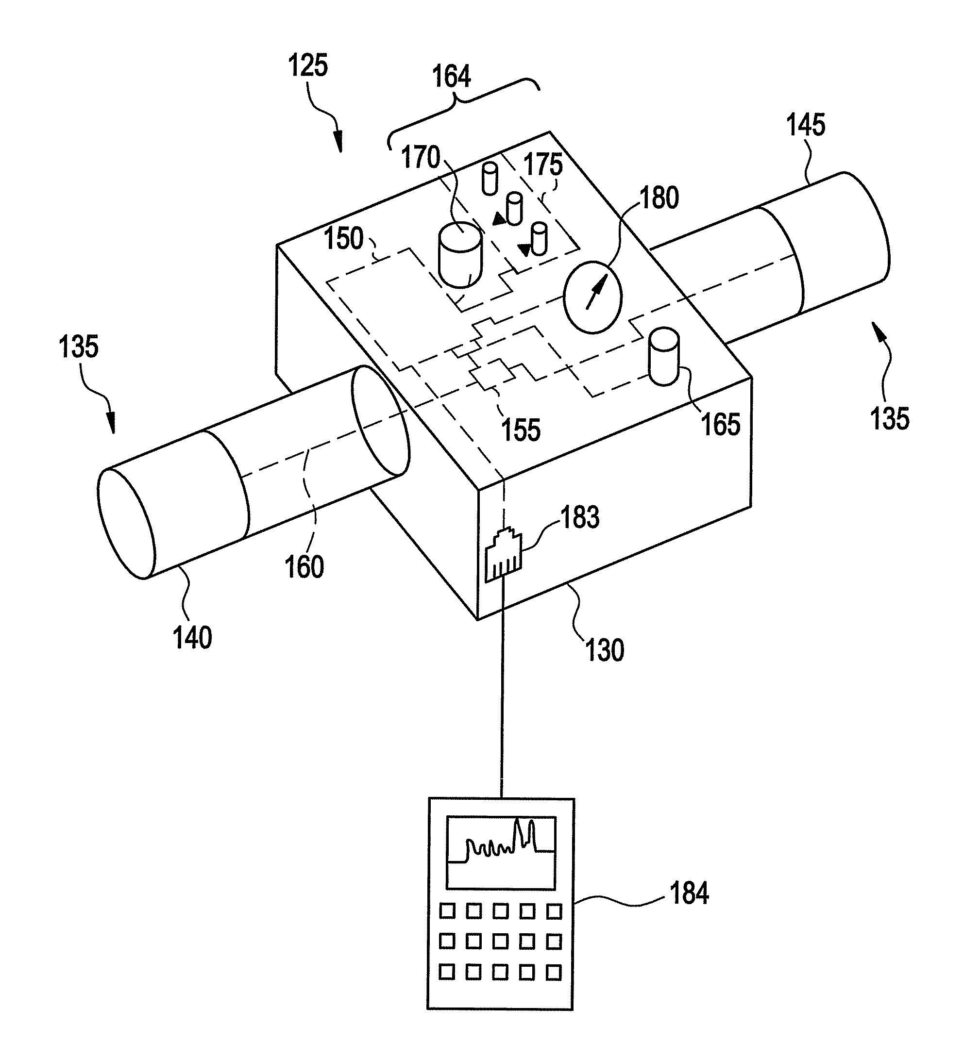
[0025]An embodiment of the invention provides an electrical protection device suitable for electrical distribution systems. The proposed device is packaged such that it can be retrofitted for use within existing fuse holders, or to replace existing fuse applications. Use of micro electromechanical system (MEMS) switches provide fast response time, thereby facilitating diminishing the let-through energy of an interrupted fault. A Hybrid Arcless Limiting Technology (HALT) circuit connected in parallel with the MEMS switches provides capability for the MEMS switches to be opened or closed without arcing at any given time regardless of current or voltage.

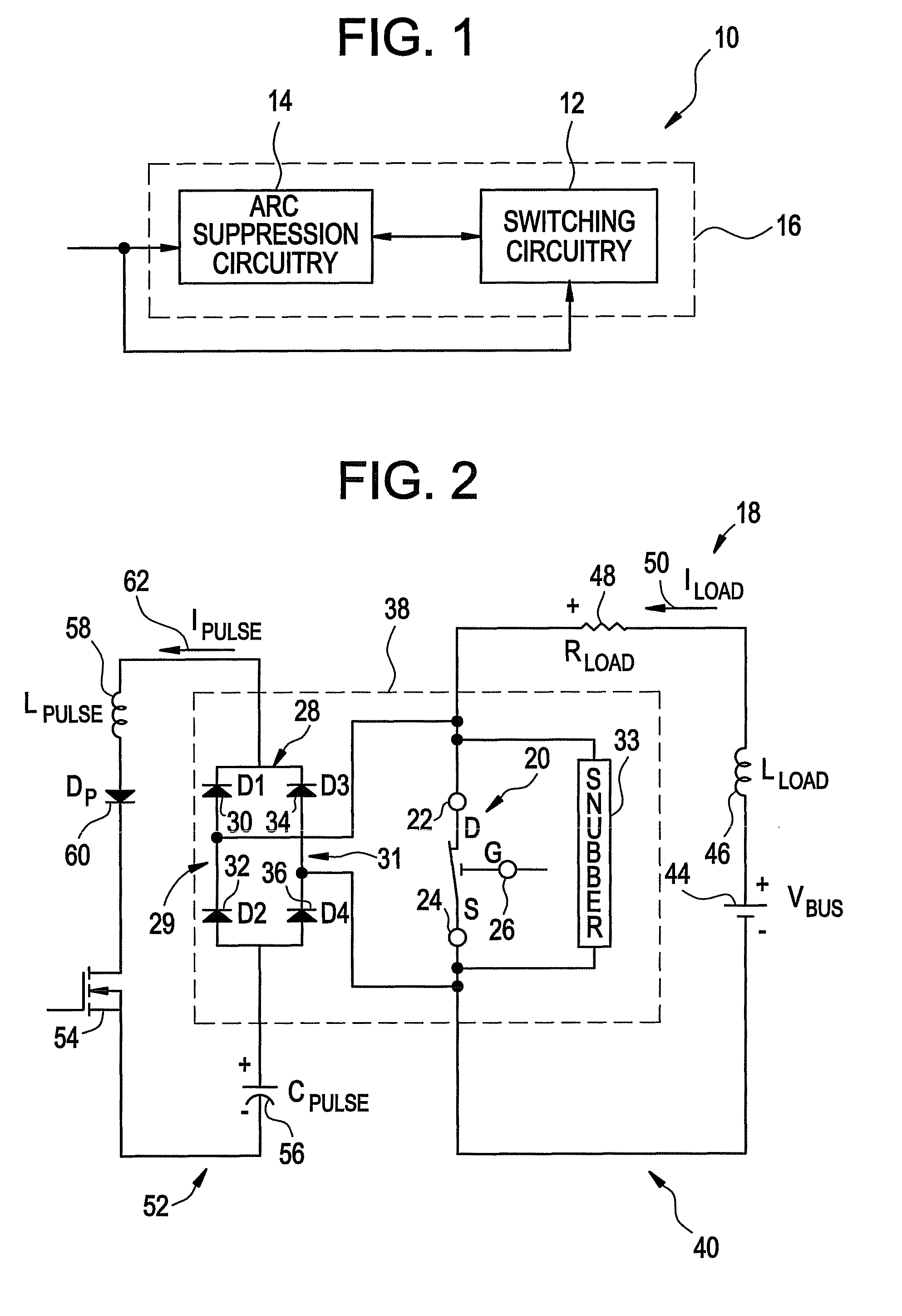
[0026]FIG. 1 illustrates a block diagram of an exemplary arc-less micro-electromechanical system switch (MEMS) based switching system 10, in accordance with aspects of the present invention. Presently, MEMS generally refer to micron-scale structures that for example can integrate a multiplicity of functionally distinct elements, for exa...


PUM


Abstract

A current control device is disclosed. The current control device includes control circuitry and a current path integrally arranged with the control circuitry. The current path includes a set of conduction interfaces and a micro electromechanical system (MEMS) switch disposed between the set of conduction interfaces. The set of conduction interfaces have geometry of a defined fuse terminal geometry and include a first interface disposed at one end of the current path and a second interface disposed at an opposite end of the current path. The MEMS switch is responsive to the control circuitry to facilitate the interruption of an electrical current passing through the current path.

Description

BACKGROUND OF THE INVENTION[0001]Embodiments of the invention relate generally to a switching device for switching off a current in a current path, and more particularly to micro-electromechanical system based switching devices.[0002]To protect against damage, electrical equipment and wiring can be protected from conditions that result in current levels above their ratings. Over-current conditions can be classified by the time required before damage occurs and may be grouped into two categories: timed over-current conditions and instantaneous over-current conditions.[0003]Timed over-current conditions or faults are deemed the less severe variety and generally require distribution protection equipment to deactivate the current path after a given time period, which depends on the level of the condition. Timed over-current faults typically include current levels just above the current rating, and may extend to and beyond 8-10 times the current rating of the distribution protection equi...

Claims


Application Information

Patent Timeline
Patent Type & Authority Patents(United States)
IPC IPC(8): H01H73/00H01H57/00H02H9/02
CPCH01H59/0009H01H71/123H01H9/40H01H9/541H01H2071/124H01H2071/008H01H2071/088
Inventor CAGGIANO, ROBERT JOSEPHPREMERLANI, WILLIAM JAMESVALDES, MARCELO ESTEBANSUBRAMANIAN, KANAKASABAPATHIKUMFER, BRENT CHARLESPITZEN, CHARLES STEPHANPARK, JOHN NORTON
Owner ABB (SCHWEIZ) AG
Why Eureka
Try Eureka