
Dispenser for viscous condiments

a condiment and dispenser technology, applied in the direction of liquid transfer devices, pliable tubular containers, liquid/fluent solid measurements, etc., can solve the problems of unnecessary disposal, affecting the appearance of the package, and adding again to the cost of containers

Active Publication Date: 2012-04-03
HUHTAMAKI INC
View PDF18 Cites 14 Cited by
  • Summary
  • Abstract
  • Description
  • Claims
  • Application Information

AI Technical Summary

Benefits of technology

The present invention is a container for dispensing viscous condiments. It has a tubular sidewall with a piston at one end and a dispensing valve assembly at the other. The valve assembly is secured to the sidewall with a mount plate and an inturned flange. The container has a removable membrane cover that can be torn open to access the valve assembly. The cover is attached to the valve assembly before being attached to the sidewall. The container is made of paperboard with a polymer coating for resistance to liquids and can be joined with heat sealing. The technical effect of this invention is a convenient and easy-to-use container for dispensing viscous condiments.

Problems solved by technology

However, to eliminate material, new assembly techniques may be needed necessitating new manufacturing equipment which adds again to the expense of the containers.
The absorption of such liquids can cause a detrimental appearance to the package and may even cause its unnecessary disposal.
Hot melt can cause detrimental generation of steam from moisture contained in various packaging components, particularly paperboard during assembly.
The steam can cause problems such as forming tiny bubbles and / or holes through the hot melt thereby permitting oil and moisture to pass into raw edges of the paperboard tube.
Thus, the tube (package) may become saturated, soften and begin to fall apart.

Method used


Image

  • Dispenser for viscous condiments
  • Dispenser for viscous condiments
  • Dispenser for viscous condiments

Examples


Embodiment Construction

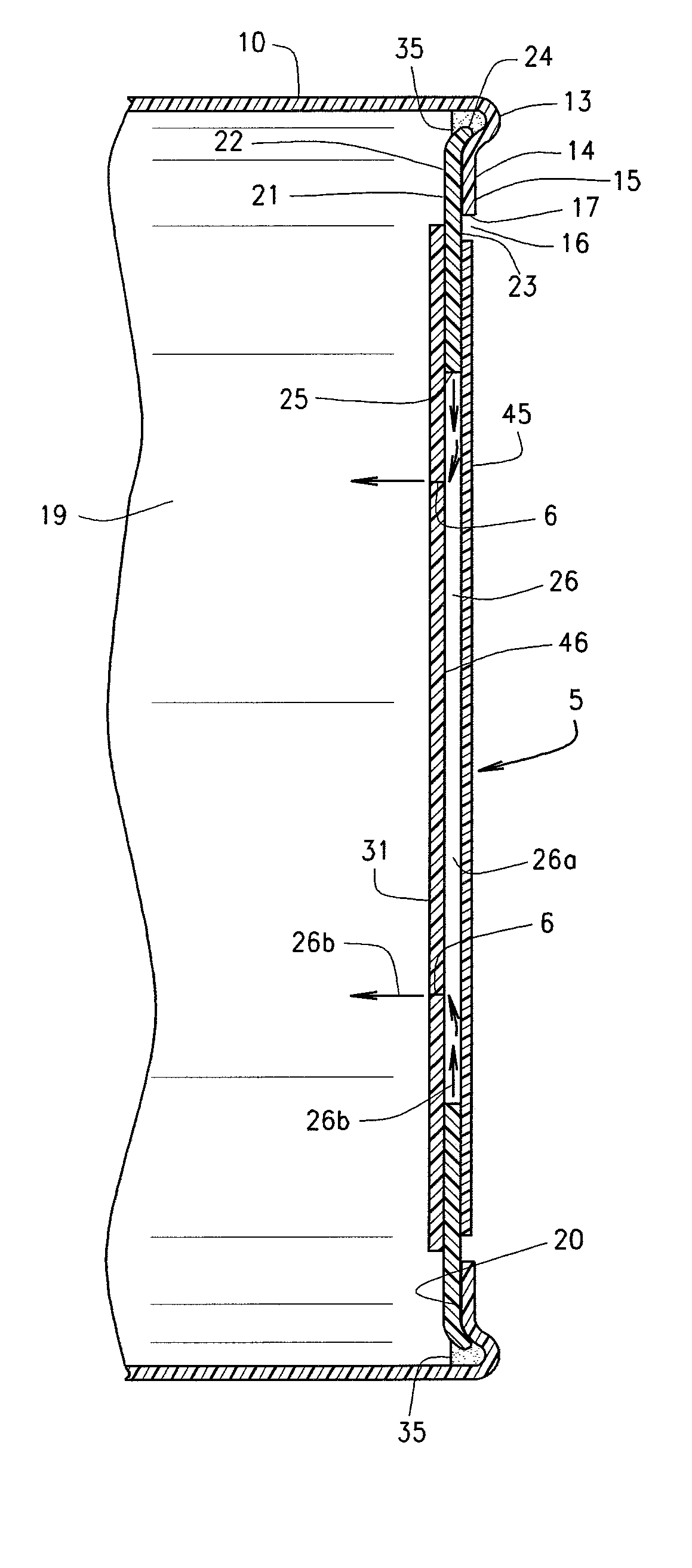
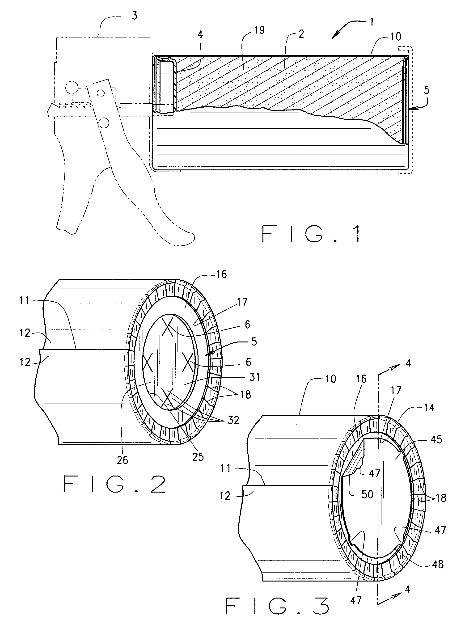
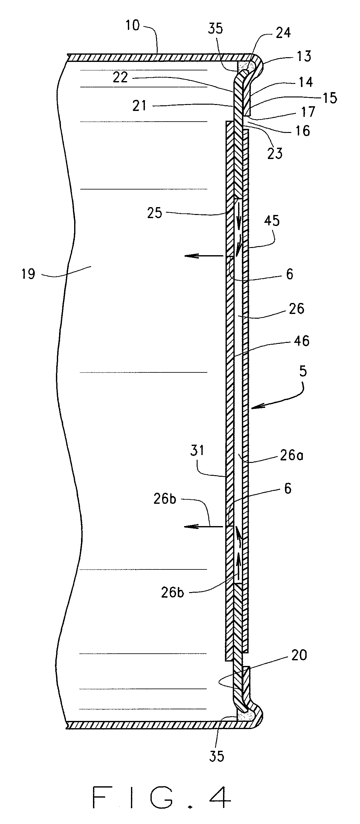
[0012]The reference numeral 1 designates generally a condiment dispenser for use in the storage and dispensing of viscous condiments 2 such as ketchup, mustard, mayonnaise, sandwich spread and the like. Such condiments 2 can be water and / or lipid based. In a preferred embodiment, the condiment dispenser 1 includes a feed device 3 that may be in the form of a trigger gun for use in applying force to a piston 4 which will in turn pressurize the condiment 2 for dispensing through a dispenser valve assembly 5 having one or more dispensing openings 6. During dispensing, the piston 4 moves toward the valve assembly 5. The feed device 3 can be manually operated for example by having a trigger or may be power operated for example by having an electric motor-driver actuator. Preferably, the feed device 3 is easily sanitized as by washing without detriment to the feed device.

[0013]The condiment dispenser 1 includes a sidewall 10 that may be formed of a polymeric-coated paperboard having a lon...


PUM

PropertyMeasurementUnit
viscousaaaaaaaaaa
forceaaaaaaaaaa
outer perimeteraaaaaaaaaa

Abstract

A dispenser is provided for viscous condiments. The dispenser includes a tubular sidewall having opposite ends. One opposite end is open and can receive a plunger or piston therein for applying force to condiment contained within a compartment inside of the sidewall. The other end of the sidewall includes a dispenser valve assembly comprising a member secured to an inturned flange portion of the sidewall with the flange portion being generally normal to the sidewall. The dispenser valve assembly is suitably secured to the flange portion as by heat sealing to form a composite laminated structure that is resistant to the penetration of liquids from the condiments. A bead of hot melt can be provided to seal an exposed outer edge of the dispenser valve assembly and to seal the dispenser valve assembly to the sidewall. The dispenser valve assembly includes a valve plate having one or more selectively openable discharge openings formed therein that will open and close under the influence of pressure applied to the condiment within the dispenser.

Description

CROSS-REFERENCE TO RELATED APPLICATIONS[0001]None.BACKGROUND OF INVENTION[0002]The dispensing of viscous condiments, e.g., mustard, ketchup, mayonnaise, sandwich spreads and the like, is commonly done in restaurants. In order to handle the volume throughput requirements in restaurant kitchens, devices have been constructed for dispensing such condiments from tubes (packages) with the assistance of mechanical pump-type devices. Such devices are similar in construction to caulking guns. An example of such a device may be found in U.S. Pat. No. 4,830,231. While such devices have been effective, they do have some shortcomings.[0003]It is desirable to eliminate material from the tubes that is not necessary. Even a small amount of material savings in a container can result in significant cost savings because of the large quantity required by restaurants, particularly in the fast food industry. However, to eliminate material, new assembly techniques may be needed necessitating new manufact...

Claims


Application Information

Patent Timeline
Patent Type & Authority Patents(United States)
IPC IPC(8): B65D88/54B67D99/00
CPCB31B1/74B65D83/0005B23P19/10Y10T29/49826Y10T29/49236Y10T29/4978B31B50/74
Inventor ROBERTSON, RONALD D.SCHNEIDER, WAYNE F.
Owner HUHTAMAKI INC
Learn More