Magnetic field detecting element including tri-layer stack with stepped portion

a magnetic field and detecting element technology, applied in the field of magnetic field detecting elements, can solve the problems of different element output characteristics, no mechanism to make the magnetization directions of the upper and lower magnetic layers, and the number of stacks that are available, so as to improve detection performance and productivity, and reduce the effect of effective read track width

Active Publication Date: 2012-04-03
TDK CORPARATION
View PDF12 Cites 3 Cited by
  • Summary
  • Abstract
  • Description
  • Claims
  • Application Information

AI Technical Summary

Benefits of technology

[0010]The present invention is directed to a magnetic field detecting element of the CPP type having a stack of a tri-layer structure. An object of the present invention is to provide a magnetic field detecting element having the layer structure described above, in which the effective read track width can be reduced. Another object of the present invention is to improve detection performance and productivity of such magnetic field detecting element.
[0012]According to this structure, the magnetization direction of a magnetic layer which has a larger length in regard to the length of an upper magnetic layer in the track width direction and the length of a lower magnetic layer in the track width direction is made parallel to the track width direction due to shape magnetic anisotropy in a state that does not have a bias magnetic field. At this time, because the upper magnetic layer and the lower magnetic layer are antiferromagnetically connected to each other by exchange coupling, the magnetization direction of the upper magnetic layer and the magnetization direction of the lower magnetic layer are made in the anti-parallel direction. Then, due to the bias magnetic field applied by a bias magnetic layer, the magnetization direction of the upper magnetic layer and the magnetization direction of the lower magnetic layer are approximately perpendicular to each other in a state that does not have an external magnetic field, and make an angle of 45° relative to the direction perpendicular to the air bearing surface, respectively. As described above, the desired magnetized state can be provided in an initial magnetization state, which allows the detection performance and the productivity of the magnetic field detecting element to be improved. Further, the effective read track width can be reduced by decreasing one of the lengths in the track width direction of the upper and lower magnetic layers.
[0013]Also, another object of the present invention is to provide a magnetic recording device in which a recording track width can be reduced. According to one embodiment of the present invention, the magnetic recording device includes the magnetic field detecting element and a discrete medium as a recording medium. Lengths in the track width direction of the upper magnetic layer and the lower magnetic layer of the stack in the magnetic field detecting element are determined dependent on the recording track width and the guard band width of the discrete medium. Accordingly, in the discrete medium having a narrow recording track width, signal outputting by the magnetic field detecting element can be maintained, and an effect due to the output of an adjacent track (crosstalk) can be controlled.

Problems solved by technology

However, there is no mechanism that will make the magnetization directions of the upper and lower magnetic layers parallel to the track width direction.
Further, when a plurality of magnetic field detecting elements is created, there also is a problem in which the output characteristics are different element-by-element because the magnetization directions in the initial magnetization state are different element-by-element.
At this time, the number of stacks that are available as the magnetic field detecting element decreases, and productivity of the magnetic field detecting element lowers.

Method used


Image

  • Magnetic field detecting element including tri-layer stack with stepped portion
  • Magnetic field detecting element including tri-layer stack with stepped portion
  • Magnetic field detecting element including tri-layer stack with stepped portion

Examples


first embodiment

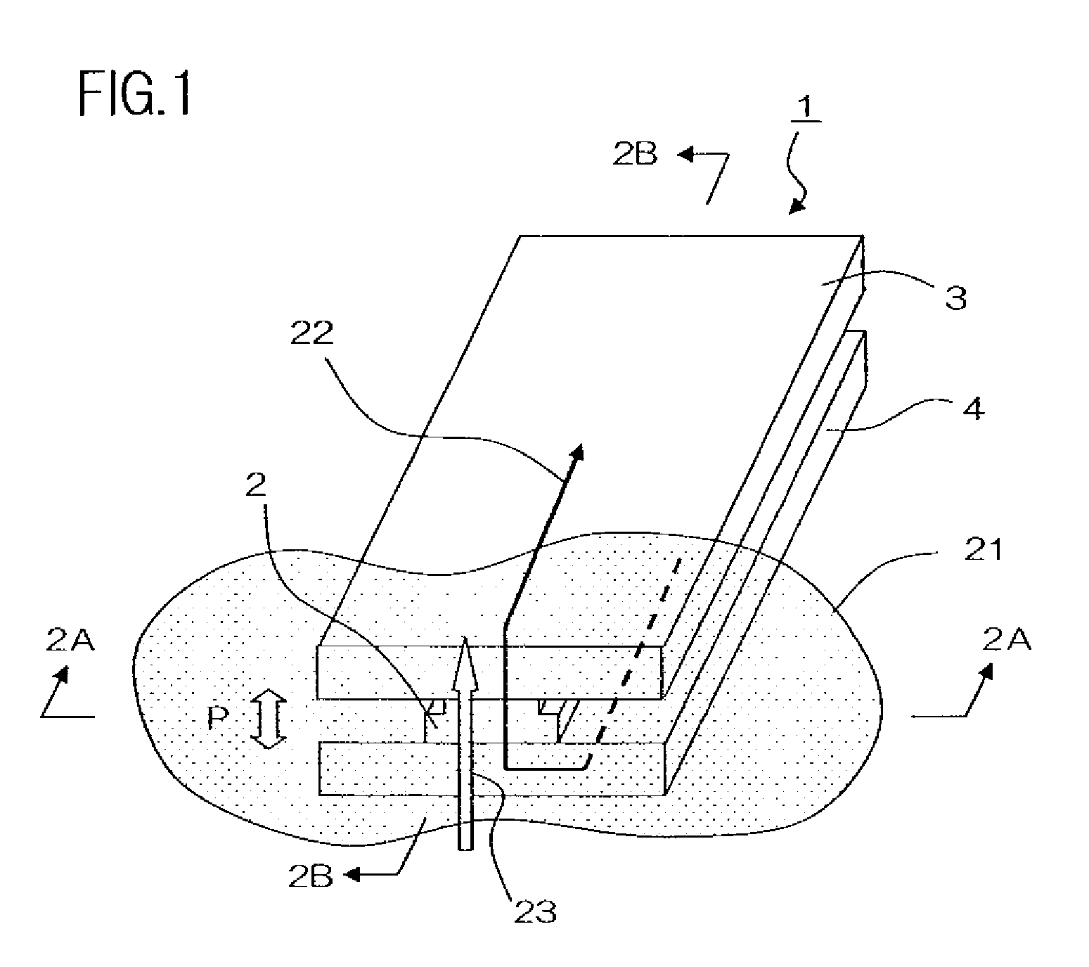
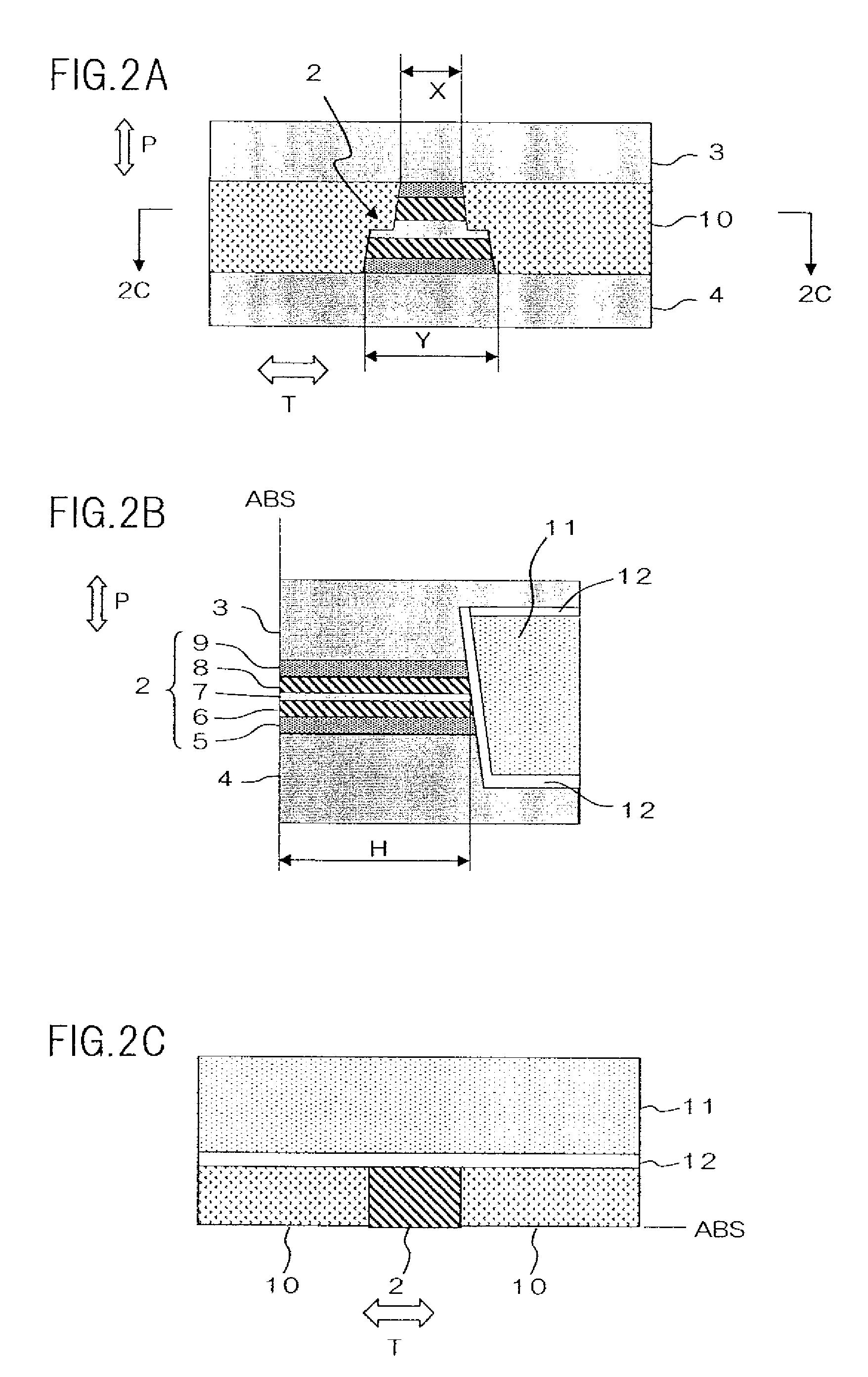
[0039]FIG. 1 is a conceptual perspective view of a magnetic field detecting element of the present embodiment. FIG. 2A is a side view of the magnetic field detecting element when viewed from the direction 2A-2A in FIG. 1, that is, an air bearing surface. FIG. 2B is a cross-section view of the magnetic field detecting element, taken along the 2B-2B line in FIG. 1. FIG. 2C is a cross-section view of the magnetic field detecting element, taken along the 2C-2C line in FIG. 2A. The Air Bearing Surface (ABS) refers to the surface of magnetic field detecting element 1 that faces recording medium 21.

[0040]Magnetic field detecting element 1 includes stack 2, upper shield electrode layer 3 and lower shield electrode layer 4 provided to sandwich stack 2 therebetween in the direction of the stacking of stack 2, bias magnetic layer 11 provided on a surface of stack 2 on the opposite side of air bearing surface ABS, and insulating layer 10 provided on both sides of stack 2 in track width directio...

second embodiment

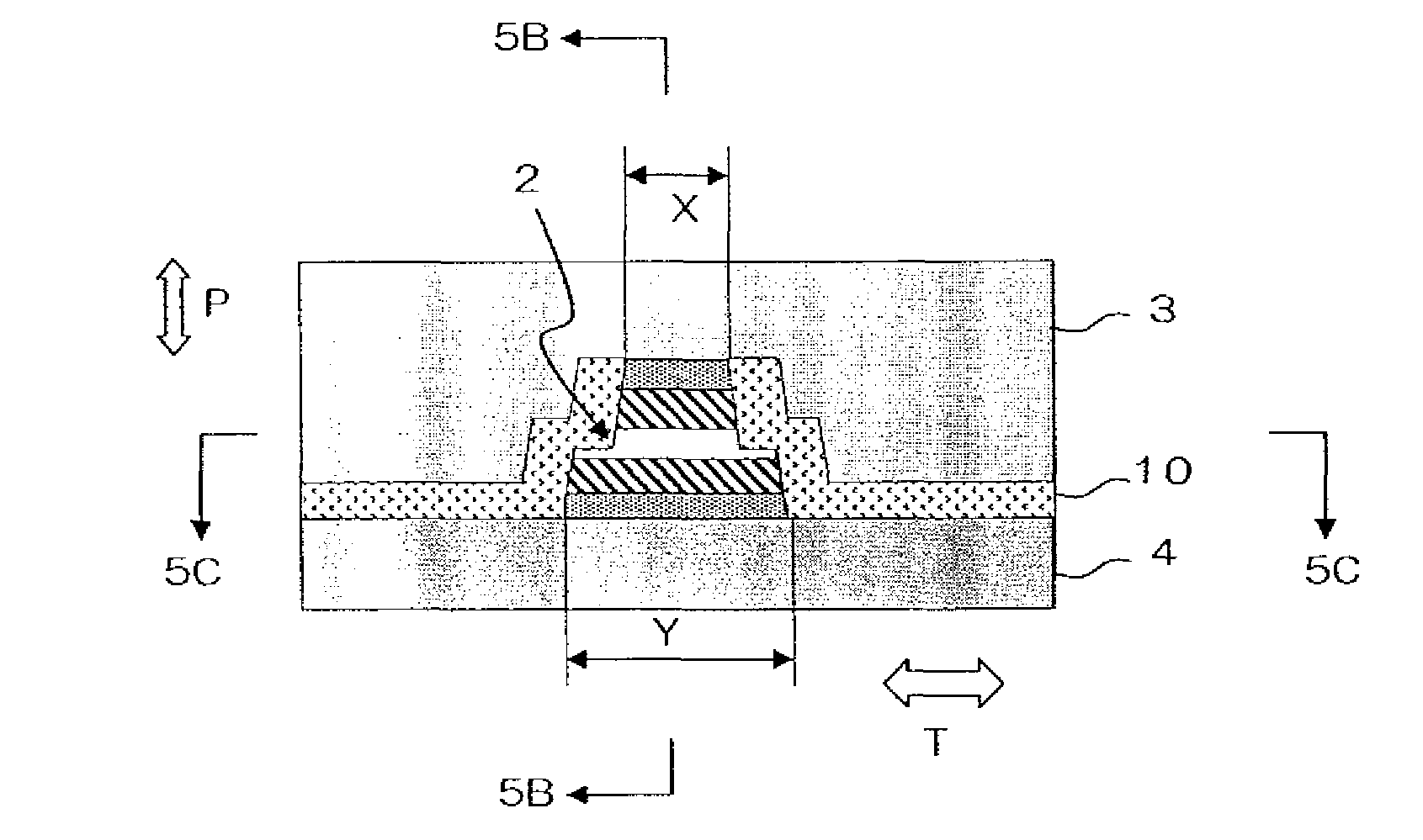
[0059]Next, a magnetic field detecting element having another structure of the present invention will be described as a second embodiment. FIG. 5A is a side view of the magnetic field detecting element according to the second embodiment when viewed from air bearing surface ABS. FIG. 5B is a cross-section view of the magnetic field detecting element, taken along 5B-5B line in FIG. 5A. FIG. 5C is a cross-section view of the magnetic field detecting element, taken along the 5C-5C line in FIG. 5A. Magnetic field detecting element 1 includes stack 2, upper shield electrode layer 3 and lower shield electrode layer 4 provided to sandwich stack 2 in the stacking direction therebetween, bias magnetic layer 11 provided on a surface of stack 2 opposite to air bearing surface ABS, and insulating layer 10 provided on both sides of stack 2 in track width direction T.

[0060]Stack 2 includes upper magnetic layer 8, lower magnetic layer 6, and non-magnetic intermediate layer 7 sandwiched between uppe...


PUM

PropertyMeasurementUnit
thicknessaaaaaaaaaa
relative angleaaaaaaaaaa

Abstract

A magnetic field detecting element comprises a stack including upper and lower magnetic layers, and a non-magnetic intermediate layer sandwiched therebetween, wherein magnetization of the magnetic layers changes in accordance with an external magnetic field; upper and lower shield electrode layers sandwiching the stack in a direction of stacking, wherein the upper and lower shield electrode layers supply sense current in the direction of stacking, and magnetically shield the stack; a bias magnetic layer provided on a surface of the stack opposite to an air bearing surface, and wherein the bias magnetic layer applies a bias magnetic field to the upper and lower magnetic layers in a direction perpendicular to the air bearing surface; and insulating layers provided on both sides of the stack in a track width direction thereof, wherein the stack has a stepped portion formed at the non-magnetic intermediate layer.

Description

BACKGROUND OF THE INVENTION[0001]1. Field of the Invention[0002]The present invention relates to a magnetic field detecting element, and in particular to an element structure of a magnetic field detecting element having a tri-layer stack.[0003]2. Description of the Related Art[0004]A thin film magnetic head used for a magnetic recording device includes a playback head having a reproducing element for read and a record head having a write element for write. As the reproducing element of the thin film magnetic head, a giant magneto resistance (GMR) element is known. Conventionally, a CIP (Current In Plane)-GMR element that makes sense current flow in a direction parallel to a film surface thereof has been mainly used. In recent years, however, an element that makes sense current flow in a direction perpendicular to a film surface thereof has been developed in order to active higher density recording. A tunnel magneto resistance (TMR) element utilizing a TMR effect, and a CPP (Current ...

Claims


Application Information

Patent Timeline
Patent Type & Authority Patents(United States)
IPC IPC(8): G11B5/39
CPCB82Y10/00B82Y25/00G11B5/3932G11B2005/3996
Inventor AYUKAWA, TOSHIYUKIMIYAUCHI, DAISUKESHIMAZAWA, KOJIMACHITA, TAKAHIKO
Owner TDK CORPARATION
Why Eureka
Try Eureka