Method for lung lesion location identification

a technology for lung lesion and location identification, applied in the field of digital imaging, can solve the problems of requiring additional time, affecting the accuracy of lung lesion location identification,

Inactive Publication Date: 2012-04-03
CARESTREAM HEALTH INC
View PDF3 Cites 12 Cited by
  • Summary
  • Abstract
  • Description
  • Claims
  • Application Information

AI Technical Summary

Problems solved by technology

Requiring the radiologist to transcribe the results for placement into the report is a source of error and also requires additional time.
If processing times are longer than the manual approach, then the advantage of the automatic method is lost and the automatic approach becomes impractical.
However, these methods require significant computational resources and are inefficient.
However, to identify the lobar location of a lung lesion, there is only a need to perform the labeling for a single or small number of voxels at the location of the lesion, and so the additional labeling effort is not utilized.
While in theory the method would produce complete lung lobar labeling, it would however lead to an inferior result in terms of overall computational efficiency.
However, the methods also require considerable computational resources and a wholesale use of such a measure throughout a CT examination is impractical.
Using these methods to perform a segmentation of the entire vascular structure is impractical in terms of computational cost.
This impracticality can result in an inefficient use of computational resources and longer processing times, and more importantly in ineffective use of the radiologist time.
Furthermore, since vessel tree structures inherently decrease in physical dimension as they undergo repeated subdivision, and due to the finite imaging resolution used during any medical imaging collection, the accuracy and reliability of the vessel tracking must correspondingly diminish as the tree structure is tracked to finer and finer structural levels.
Segmentation errors include, for example, spurious vessel branches due to slight vessel boundary deformations caused by image noise and artifacts, missing vessel segments, and missing branches.
Matching errors or ambiguities can arise as a result of segmentation errors and also as a result of normal or abnormal anatomical variations in the human population.
However, there may arise circumstances in which the use of the bronchial tree cannot successfully localize a lesion, most likely due to difficulty in tracing back from the lesion to the main bronchi, as described below, or due to pulmonary disease.

Method used


Image

  • Method for lung lesion location identification
  • Method for lung lesion location identification
  • Method for lung lesion location identification

Examples


Embodiment Construction

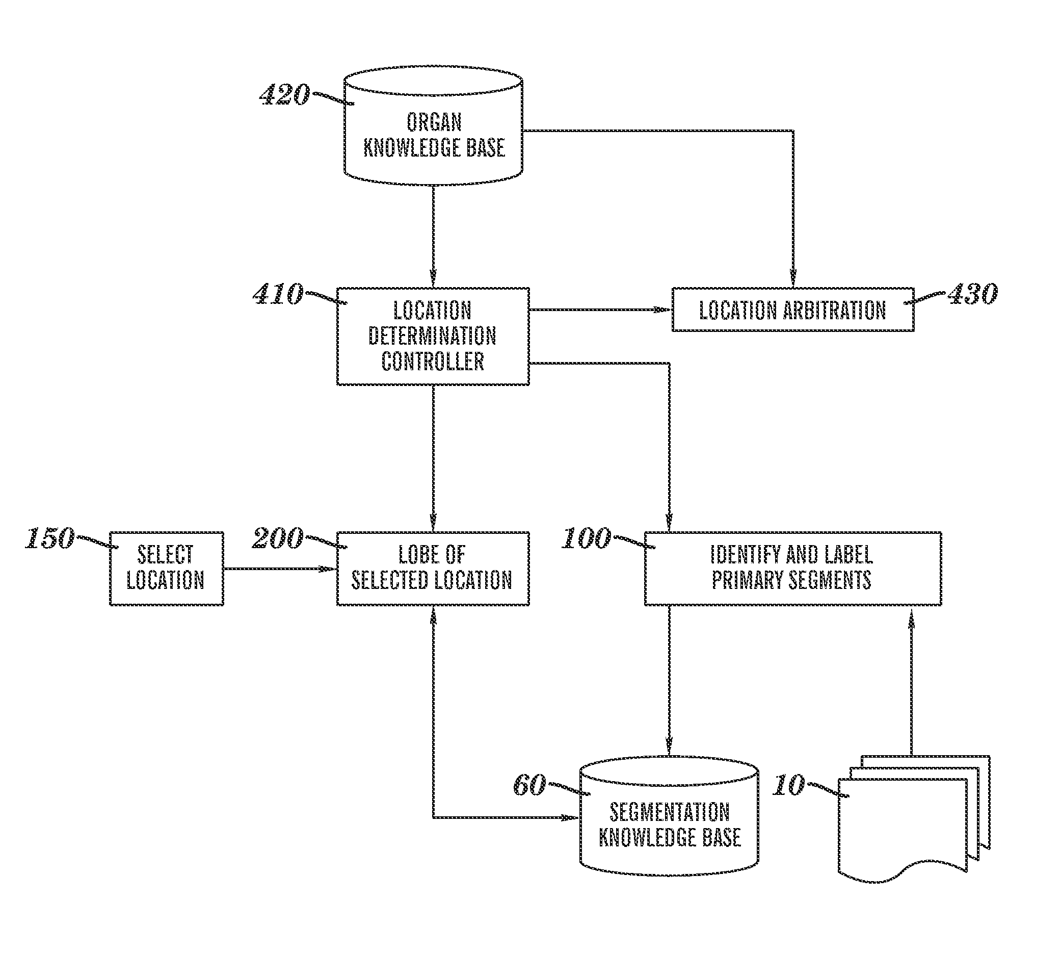
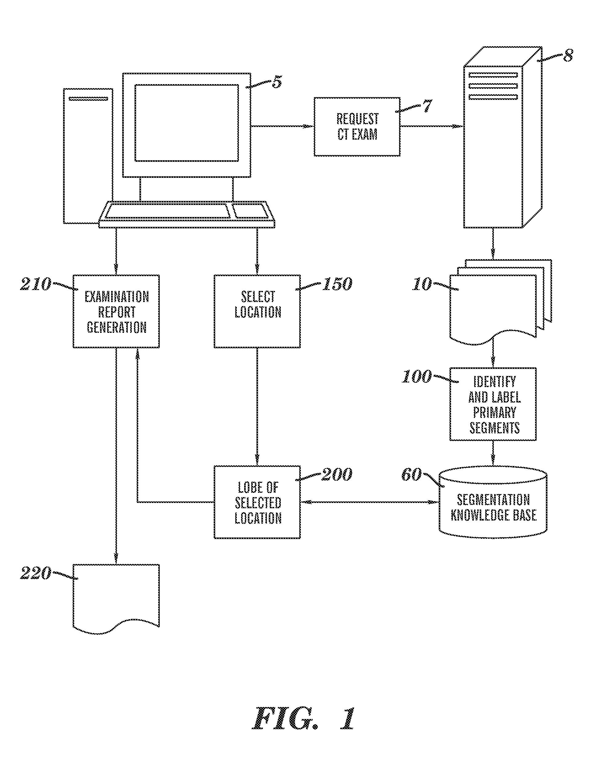
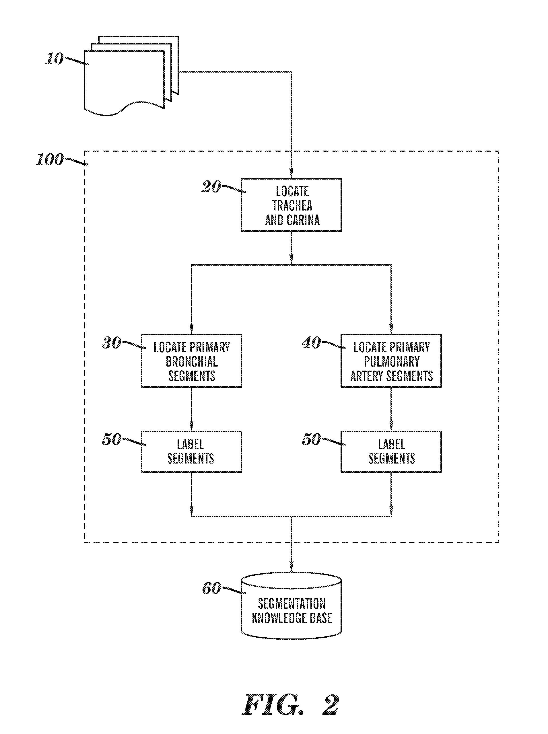
[0031]Reference is made to commonly-assigned co-pending U.S. patent application Ser. No. 11 / 567,857, filed Dec. 7, 2006 entitled ANALYZING LESIONS IN A MEDICAL DIGITAL IMAGE, by Simon et al., the disclosure of which is incorporated herein.

[0032]As disclosed in the background above, the embodiments of the pre-sent invention can be applied broadly to anatomical organs and organ systems of interest in cases where there are associated to the organs or systems a hierarchical vessel tree structure that supplies, for example, blood or ambient air with oxygen. Some of the detailed description below will be specified to the case of the human lungs for purposes of concrete illustration. It will be clearly understood by persons skilled in the ordinary art that such specification is performed for teaching purposes only, does not restrict the application of the invention to other qualifying organs or organ systems, nor does such specification preclude the use of the invention in the field of non...


PUM


Abstract

A method and a system are disclosed for labeling an anatomical point associated with a lesion in an organ such as a lung. The method includes: a segmentation of a vessel tree anatomical structure starting from an autonomously determined initial image point; labeling the vessel segments of the vessel tree segmentation with segment labels based on a priori anatomical knowledge, thereby creating an individualized anatomical model; receiving a user-specified image point having a location from a user and locating a nearby vessel structure; tracking along the vessel structure in a direction towards a root of a parent vessel tree until a prior labeled vessel segment is encountered in the anatomical model, and assigning the label of the encountered prior labeled vessel segment from the anatomical model as an anatomical location label of the user-specified image point.

Description

FIELD OF THE INVENTION[0001]The embodiments of the present invention relate to the field of digital imaging, and more particularly to processing a 3D digital medical image to identify and report the location of an anatomical object.BACKGROUND OF THE INVENTION[0002]Identification of potentially cancerous lesions in CT and MRI studies is a common task of radiologists. Once such a lesion has been identified, it is desirable to determine information pertaining to the lesion, such as the extent and the volume such a lesion occupies and other descriptors. The radiologist's report documents the findings of the examination. Part of this report contains the location of the lesion and this is usually reported relative to anatomical structures or landmarks. The use of anatomical landmarks is preferred as the basic anatomy is common to all patients and is independent of the particular examination conducted.[0003]The visual interpretation of the examination by the radiologist can be done in conj...

Claims


Application Information

Patent Timeline
Patent Type & Authority Patents(United States)
IPC IPC(8): G06K9/30G06K9/34G06V30/144
CPCG06T7/0012G06T7/0083G06T7/0089G06T7/0093G06T2207/10081G06T2207/10088G06T2207/20101G06T2207/30061G06T2207/30101Y10S128/92Y10S128/922Y10S128/923G06T7/12G06T7/149G06T7/162
Inventor RAY, LAWRENCE A.SIMON, RICHARD A.NICPONSKI, HENRYGINDELE, EDWARD B.
Owner CARESTREAM HEALTH INC
Why Eureka
Try Eureka