Turbulizers and method for forming same

a technology of turbulizers and turbulizers, which is applied in the direction of manufacturing tools, lighting and heating apparatus, and shaping tools, etc., can solve the problems of low corrugation amplitude to pitch ratio, low offset distance, and relatively slow process, and achieve low pressure drop in use, high ratio of corrugation amplitude, and convenient operation

Active Publication Date: 2012-04-10
DANA CANADA CORP
View PDF9 Cites 16 Cited by
  • Summary
  • Abstract
  • Description
  • Claims
  • Application Information

AI Technical Summary

Benefits of technology

[0009]The methods permit the relatively inexpensive construction of the apparatus. The structures can have substantially vertical bridge sidewalls, can have offset corrugations having a relatively high ratio of corrugation amplitude to pitch, can produce a relatively low pressure drop in use and can have relatively large offsets.

Problems solved by technology

Accordingly, this process is relatively slow and expensive.
Further, as there are practical limits in terms of the amount by which the material can be deformed during stamping without fracture, turbulizers produced by this method typically have a relatively low ratio of corrugation amplitude to pitch and relatively low offset distance.
US2005 / 0016240, published Jan. 27, 2005, which publication is hereby incorporated by reference, is relatively fast and inexpensive, but turbulizers of sinusoidal profile are not always desired since they can be difficult to produce in balanced form and do not provide the same burst strength as turbulizers with vertical corrugation sidewalls.

Method used


Image

  • Turbulizers and method for forming same
  • Turbulizers and method for forming same
  • Turbulizers and method for forming same

Examples


Embodiment Construction

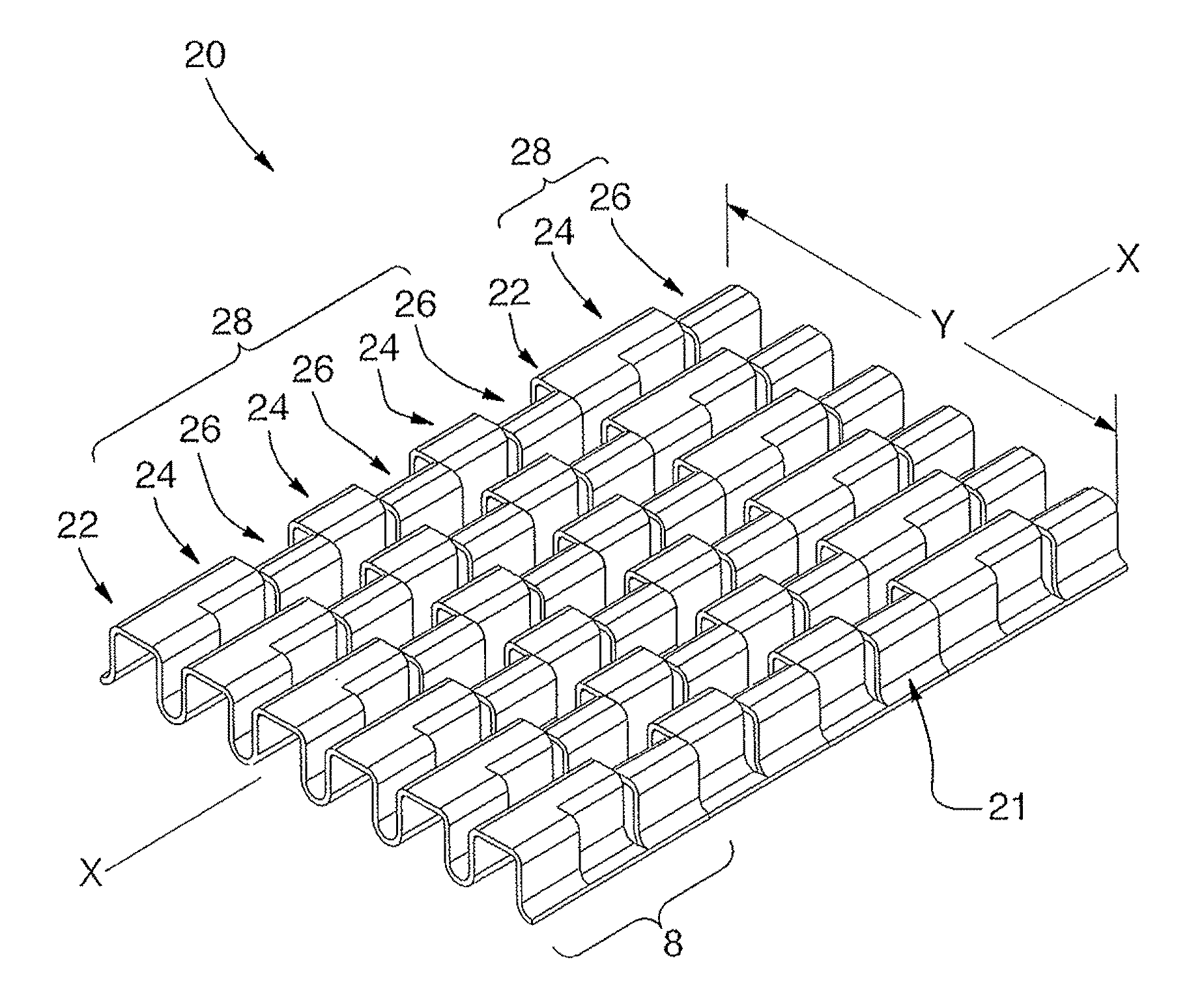
[0048]A turbulizer or fin apparatus 20 for a heat exchanger forms one aspect of the invention and is hereinafter described with reference to FIG. 4, wherein an exemplary turbulizer 20 according to the invention is shown, and with reference to FIGS. 8, 18-21 and 28, wherein a structure which corresponds to bracketed portion 8 of FIG. 4 is shown.

[0049]The turbulizer structure 20 will be seen to comprise a member, designated with general reference numeral 21, having a longitudinal axis X-X, a lateral width Y and a plurality of strips 22,24,26. Member 21 takes the form of a 0.010″ inch aluminum sheet material. The plurality of strips 22,24,26 includes first strips 24, second strips 26 and third strips 22. The first strips 24 and the second strips 26 are arranged in groupings 28, wherein they are arranged in longitudinally-alternating relation to one another. The third strips 22 are separated from one another by the groupings 28.

[0050]With reference to FIGS. 4, 8 and 18, each strip 22,24...


PUM

PropertyMeasurementUnit
widthaaaaaaaaaa
pressure dropaaaaaaaaaa
corrugation amplitudeaaaaaaaaaa

Abstract

Disclosed is a method of forming a heat exchanger turbulizer apparatus including a member having a longitudinal axis, a lateral width and a plurality of strips including first strips and second strips, each strip extending widthwise and being corrugated longitudinally so as to form a plurality of laterally spaced-apart sections connected to one another by bridges projecting from the sections in a common direction, the bridges of the first and second strips extending in the same direction and the corrugations of the second strips being offset laterally from the corrugations of the first strips. The method comprises: crimping longitudinally-corrugated strip material between first and second forming dies to form said apparatus, said dies being adapted such that substantially all lateral movement of strip material in crimping results from strip material being drawn laterally by material that has been displaced in a direction parallel to the direction of die movement.

Description

FIELD OF THE INVENTION[0001]The present invention relates to fins or turbulizers, for example, for heat exchangers, and to methods for forming same.BACKGROUND OF THE INVENTION[0002]It is known to manufacture low pressure drop (LPD) turbulizers by stamping metal strip stock to form it with transverse corrugations having openings and offset portions formed in side walls of the corrugations. In known stamping processes, a single transverse corrugation is created by each stamp cycle. Accordingly, this process is relatively slow and expensive. Further, as there are practical limits in terms of the amount by which the material can be deformed during stamping without fracture, turbulizers produced by this method typically have a relatively low ratio of corrugation amplitude to pitch and relatively low offset distance. However, known transverse-stamping processes of this type are nonetheless widely used, as same permit the manufacture of turbulizers of high utility, flowing from the geometr...

Claims


Application Information

Patent Timeline
Patent Type & Authority Patents(United States)
IPC IPC(8): B21D53/04B21D13/02F28F13/12
CPCB21D53/04F28F1/128F28F13/12F28F3/027Y10T29/4935
Inventor FENG, YIZURAWEL, PETERCARON, RAY
Owner DANA CANADA CORP
Why Eureka
Try Eureka