Flexible ignitor assembly for air/fuel mixture and method of construction thereof

a technology of air/fuel mixture and ignitor assembly, which is applied in the direction of spark plugs, machines/engines, manufacturing tools, etc., can solve the problems of not being able to accommodate a straight and/or partially obstructed ignitor opening, and achieve the effect of reducing the size, weight and cost of the overall engine, and efficient utilization of the available space in the cylinder head

Active Publication Date: 2012-04-10
FEDERAL MOGUL IGNITION
View PDF33 Cites 6 Cited by
  • Summary
  • Abstract
  • Description
  • Claims
  • Application Information

AI Technical Summary

Benefits of technology

[0007]Accordingly, the intermediate region allows the flexible ignitor assembly to be freely disposed in bent, multi-axis or partially obstructed ignitor holes in a cylinder head of an engine. Further, designers of the cylinder head and overall ignition systems are free to utilize less space and introduce complex, partially obstructed, or multi-axes bores, if necessary, to house the ignitor assembly without concern for accommodating installation of the ignitor assembly along a straight path. The efficient utilization of available space in a cylinder head and throughout the ignition system, as a result of the flexible ignitor assembly, contributes to a decrease in the size, weight and cost of the overall engine.

Problems solved by technology

However, it is not able to accommodate a non-straight and / or a partially obstructed ignitor opening.

Method used


Image

  • Flexible ignitor assembly for air/fuel mixture and method of construction thereof
  • Flexible ignitor assembly for air/fuel mixture and method of construction thereof
  • Flexible ignitor assembly for air/fuel mixture and method of construction thereof

Examples


Embodiment Construction

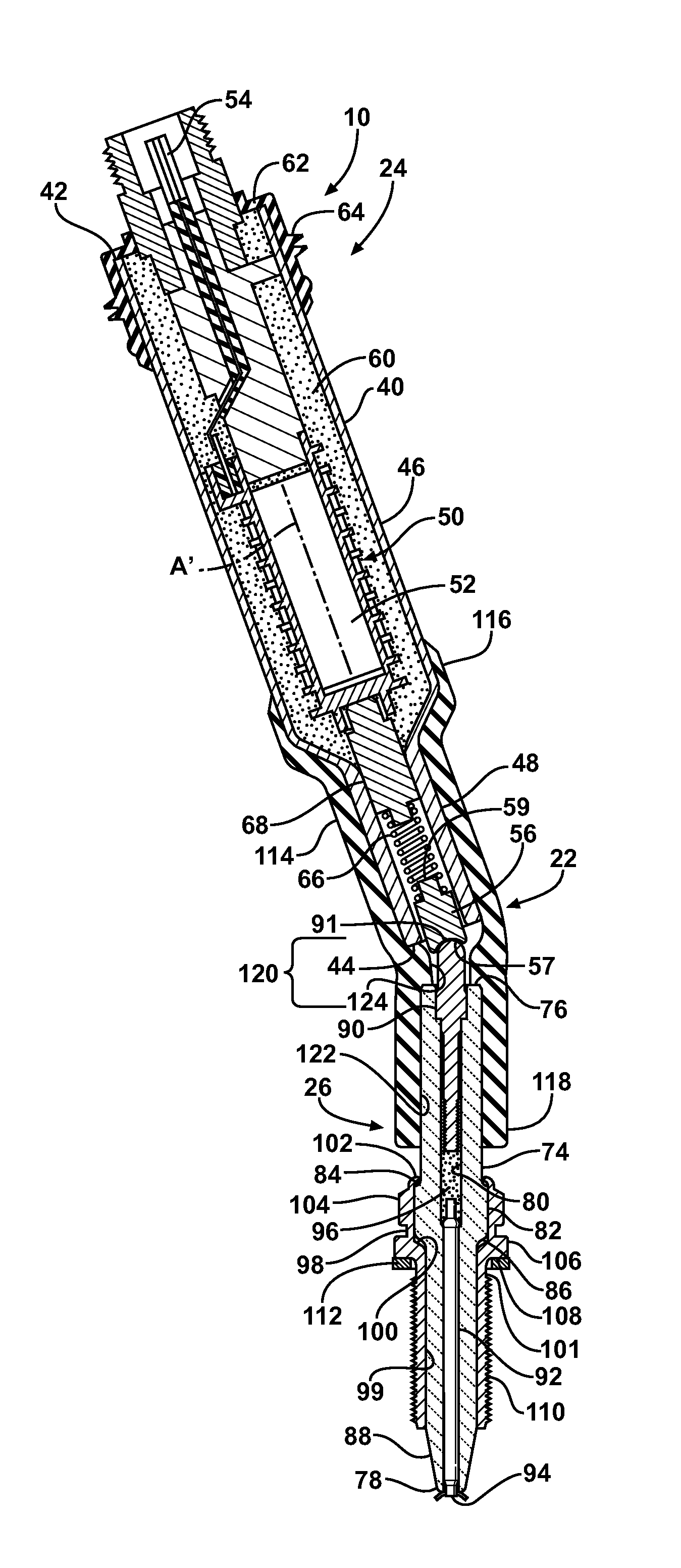
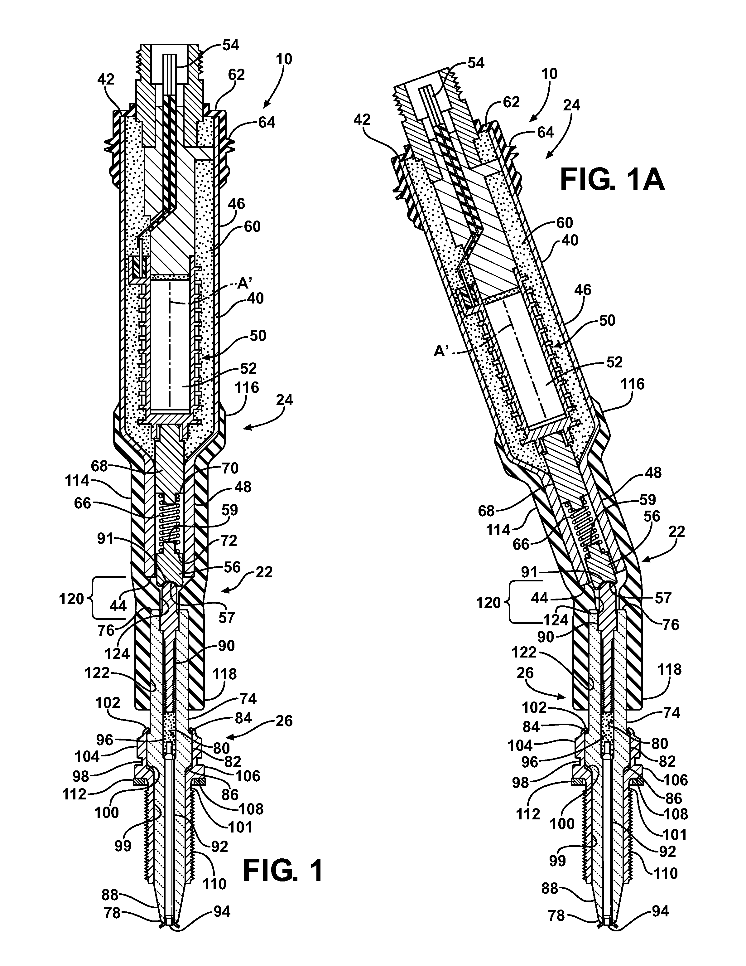
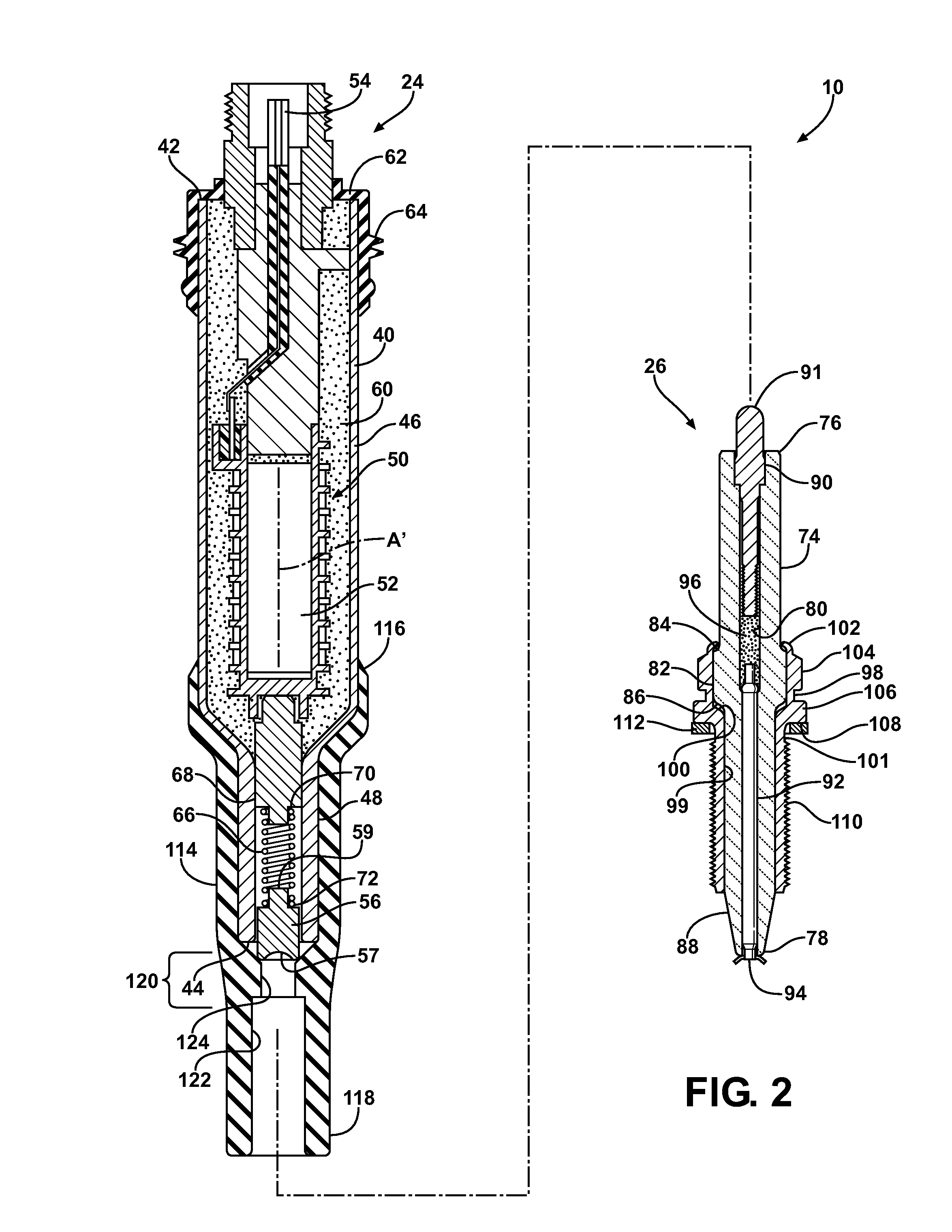
[0014]FIGS. 1-3 show an ignitor assembly, represented as a corona discharge ignitor assembly, and referred to hereafter as assembly 10, constructed in accordance with one aspect of the invention. As shown in FIG. 3, the assembly 10 is constructed to be mounted within an ignitor bore 12 of a cylinder head 14 that is configured to be joined to an engine block 16 of an internal combustion engine 18. The engine block 16 includes a combustion cylinder 20 in which a piston (not shown) reciprocates. The engine 18 may have a plurality of such combustion cylinders 20 and associated pistons. The ignitor bore 12 can be constructed to extend along a straight axis, or, if desired, along multiple non-parallel axes, such as may be desired to route around other adjacent engine features, such as a fuel injector bore 19 in which a fuel injector head (not shown) is received for injecting a fuel / air mixture into the combustion cylinder 20 and / or a valve bore 21 in which a valve assembly 23 is received,...


PUM

PropertyMeasurementUnit
electricalaaaaaaaaaa
dielectric strengthaaaaaaaaaa
diameteraaaaaaaaaa

Abstract

An ignitor assembly constructed in accordance with one aspect of the invention has an upper inductor subassembly coupled to a lower firing end subassembly for relative pivot movement between the subassemblies. The upper inductor subassembly includes a tubular housing with inductor windings received therein with an upper electrical connector adjacent an upper end of the housing and a lower electrical connector adjacent a lower end of the housing. The lower firing end subassembly includes a ceramic insulator and a metal housing surrounding at least a portion of the ceramic insulator. The ceramic insulator has an electrical terminal extending from a terminal end and an electrode extending from a firing end. A flexible tube couples the upper inductor subassembly to the lower firing end subassembly and maintains the electrical terminal of the lower firing end subassembly in electrical contact with the lower electrical connector of the upper at a pivot joint.

Description

CROSS-REFERENCE TO RELATED APPLICATION[0001]This application claims the benefit of U.S. Provisional Application Ser. No. 61 / 143,994, filed Jan. 12, 2009, which is incorporated herein by reference in its entirety.BACKGROUND OF THE INVENTION[0002]1. Technical Field[0003]This invention relates generally to ignitors used for igniting air / fuel mixtures in automotive application and the like.[0004]2. Related Art[0005]U.S. Pat. No. 6,883,507 discloses an ignitor for use in a corona discharge air / fuel ignition system. The ignitor is straight and is able to fit in ignitor openings that are straight. However, it is not able to accommodate a non-straight and / or a partially obstructed ignitor opening.SUMMARY OF THE INVENTION[0006]An ignitor assembly constructed in accordance with one aspect of the invention has an upper inductor subassembly including a tubular housing extending between an upper end and a lower end with inductor windings received therein and an upper electrical connector adjacen...

Claims


Application Information

Patent Timeline
Patent Type & Authority Patents(United States)
IPC IPC(8): F02P3/02H01T13/02
CPCH01T13/04H01T13/44Y10T29/49904Y10T29/49002H01T13/02H01T13/20
Inventor LYKOWSKI, JAMES DHAMPTON, KEITH
Owner FEDERAL MOGUL IGNITION
Why Eureka
Try Eureka