Three-way connector for cabinet frame

a three-way connector and cabinet frame technology, applied in the direction of rod connections, dismountable cabinets, couplings, etc., can solve the problems of frame easily deformation, poor positioning, inability to ensure accurate installation dimensions, etc., to achieve convenient connection, accurate positioning, and great intensity

Inactive Publication Date: 2012-04-10
SHEN SUIZHANG
View PDF7 Cites 10 Cited by
  • Summary
  • Abstract
  • Description
  • Claims
  • Application Information

AI Technical Summary

Benefits of technology

[0008]Advantages of the invention include: 1) the connector is made of Q235B-type steel (referring to China National Standard) that having the same material with the cabinet frame, which makes it convenient to connect the invention to the cabinet frame, and features great intensity, accurate positioning, and convenient field production; 2) the installation hole corresponding to the frame is disposed on the body, the three-way connector connects sections of two types of cabinet frames altogether, and thus the sections are accurately positioned, then the cabinet frames are formed via welding, the section is connected to the three-way connector via a hexagonal nut, and the M12 tapping hole disposed at the top thereof is for installation of a ring of the cabinet; 3) the invention ensures accurate welding and positioning of the cabinet frame, and improves intensity of the frame whereby making it not easy to deform; 4) processing of cutting corners of the section is not required, which reduces production processes; 5) the cabinet frame has good appearance after welding, and installation of other components of the cabinet is ensured.

Problems solved by technology

However, the frame easily deforms, features poor positioning, and cannot ensure accurate installation dimensions.

Method used


Image

  • Three-way connector for cabinet frame
  • Three-way connector for cabinet frame
  • Three-way connector for cabinet frame

Examples


Embodiment Construction

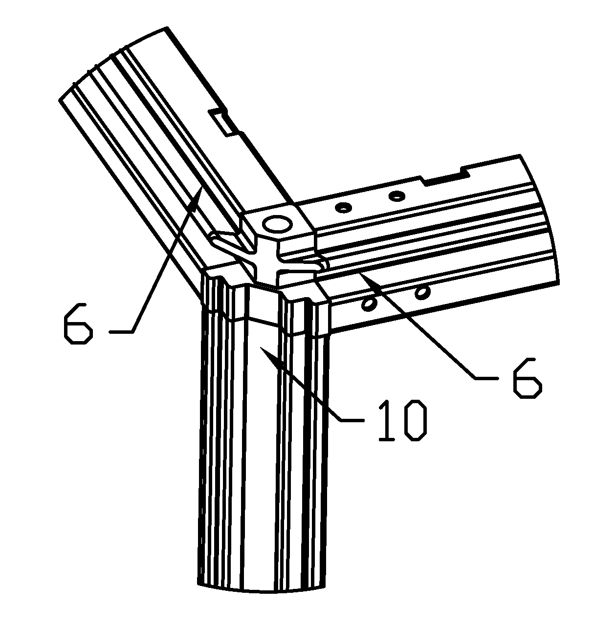
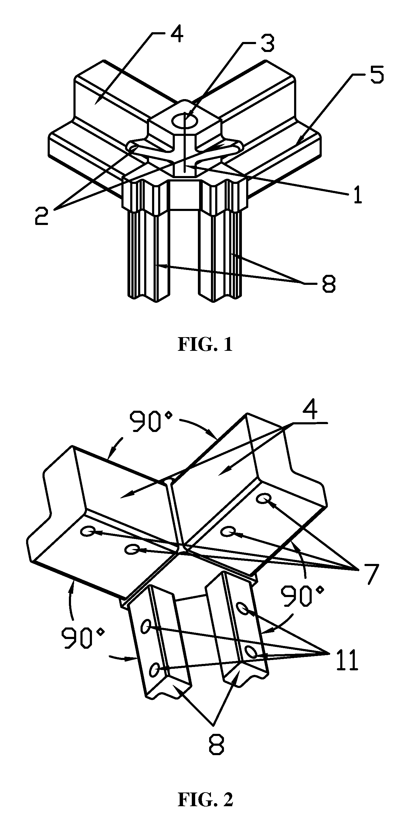
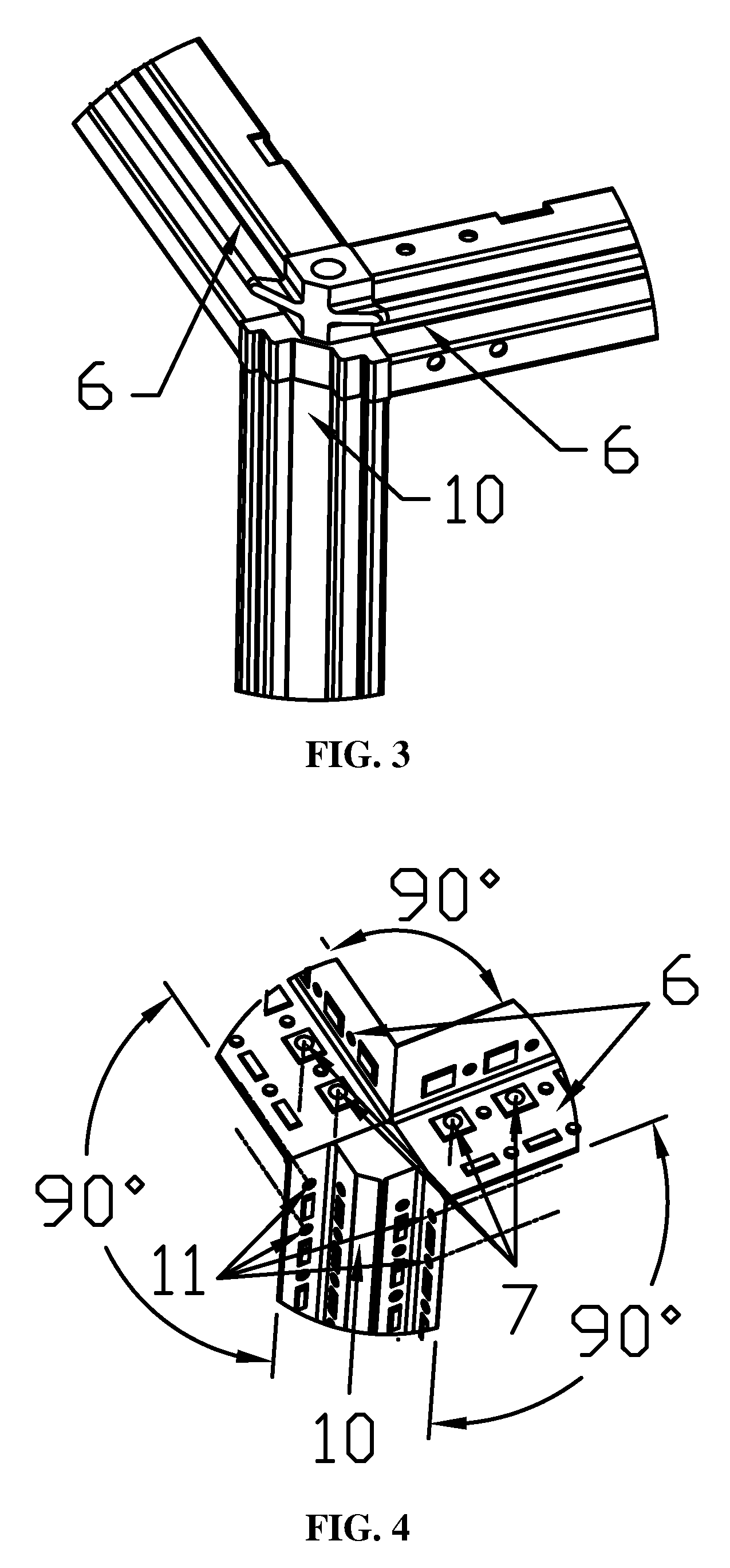
[0013]As shown in FIGS. 1-4, a three-way connector for a cabinet frame comprises a body 1, multiple positioning columns 4, and 8, a pair of M6 tapping holes 7, a pair of M6 tapping holes 11, a M12 tapping hole 3, a ten-folded section 6, and a fifteen-folded section 10.

[0014]A shape of the body 1 corresponds to that of the cabinet frame.

[0015]A pair of triangular corners 2 is disposed on both sides of the body 1, whereby ensuring good appearance of the cabinet frame after welding, and matching between the cabinet frame and the fifteen-folded section.

[0016]The M12 tapping hole 3 is disposed at the top of the body 1, which makes it convenient for installation of a ring of the cabinet.

[0017]The positioning columns 4 is fit with a cavity of the ten-folded section 6, and an angle between the positioning columns 4 is 90 degrees, which ensure accurate positioning thereof.

[0018]The M6 tapping holes 7 are disposed on the positioning columns 4, and fit with an installation hole of the ten-fold...


PUM


Abstract

A three-way connector for a cabinet frame, including a body 1, multiple positioning columns 4, 8, a pair of M6 tapping holes 7, a pair of M6 tapping holes 11, a M12 tapping hole 3, a ten-folded section 6, and a fifteen-folded section 10. A pair of triangular corners 2 is disposed on both sides of the body 1. The M12 tapping hole 3 is disposed at the top of the body 1. The positioning columns 4 are fit with a cavity of the ten-folded section 6. The M6 tapping holes 7 are disposed on the positioning columns 4, and fit with an installation hole of the ten-folded section 6. The positioning columns 8 are fit with a cavity of the fifteen-folded section 10, and are parallel to each other. The M6 tapping holes 11 are disposed on the positioning columns 8.

Description

CROSS-REFERENCE TO RELATED APPLICATIONS[0001]This application is a continuation of International Patent Application No. PCT / CN2009 / 072354 with an international filing date of Jun. 19, 2009, designating the United States, now pending, and further claims priority benefits to Chinese Patent Application No. 200810151946.2 filed on Sep. 28, 2008. The contents of all of the aforementioned applications, including any intervening amendments thereto, are incorporated herein by reference.BACKGROUND OF THE INVENTION[0002]1. Field of the Invention[0003]The invention relates to a component for a cabinet frame, and more particularly to a three-way connector for a cabinet frame.[0004]2. Description of the Related Art[0005]With development of high or low voltage distribution industries, and increase in requirements for technical performance thereof such as practice, safety and so on, requirements for performance of a cabinet section are increasingly high, and therefore requirements for forms, posit...

Claims


Application Information

Patent Timeline
Patent Type & Authority Patents(United States)
IPC IPC(8): A47B43/00
CPCH02B1/01H02B1/014Y10T403/347Y10T403/342Y10T403/341
Inventor SHEN, SUIZHANG
Owner SHEN SUIZHANG
Why Eureka
Try Eureka