
Screenless granular media filters and methods of use

a filter and granular media technology, applied in the direction of moving filter element filters, filtration separation, separation processes, etc., can solve the problems of no longer effectively removing suspended solids from the incoming liquid, the filter media eventually becomes saturated with suspended solids, and the backwashing can be very time-consuming and laborious

Inactive Publication Date: 2012-04-10
ALFA LAVAL ASHBROOK SIMON HARTELY INC
View PDF217 Cites 10 Cited by
  • Summary
  • Abstract
  • Description
  • Claims
  • Application Information

AI Technical Summary

Benefits of technology

"The present disclosure describes a continuous, self-cleaning liquid filtering apparatus that includes a vessel with a bed of filtration material, an intake for introducing unfiltered liquid, a washbox assembly, an effluent riser pipe, and a deflector. The apparatus is designed to filter liquids without the need for a screen and uses a stratification system to improve the filtering process. The apparatus can be used in various industries such as power generation, chemical production, and waste treatment. The technical effects of the invention include improved filtering efficiency, reduced energy consumption, and reduced waste production."

Problems solved by technology

The filter media eventually becomes saturated with suspended solids and no longer effectively removes suspended solids from the incoming liquid.
Backwashing can be very time consuming and generates large volumes of wastewater.
Additionally, filtered solids are never completely removed from the filter media during backwashing, which eventually results in the filter media needing to be replaced.
The above-described continuous systems for the filtration of liquids and the removal of suspended solid granules are typically not as effective or efficient as industry desires.
One problem that remains is the corrosion of metallic screens in the screen cartridges, for example when brines are processed in a vertical granular media filter such as described above.
While various plastic screens have tried, they have met with limited success, primarily due to insufficient strength of plastic screens, and the added cost of engineering special screens for specific applications.

Method used


Image

  • Screenless granular media filters and methods of use
  • Screenless granular media filters and methods of use
  • Screenless granular media filters and methods of use

Examples


embodiment 100

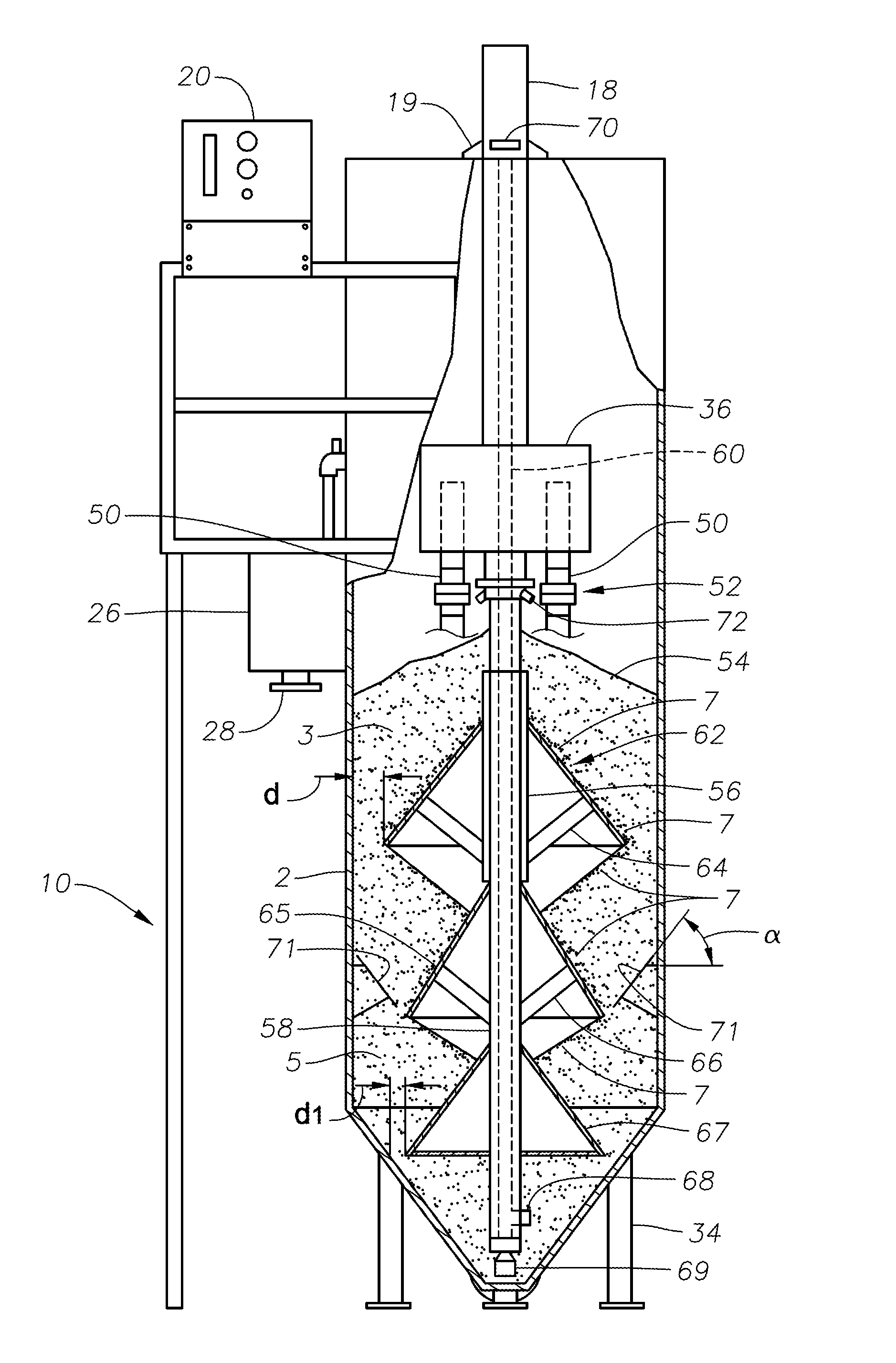
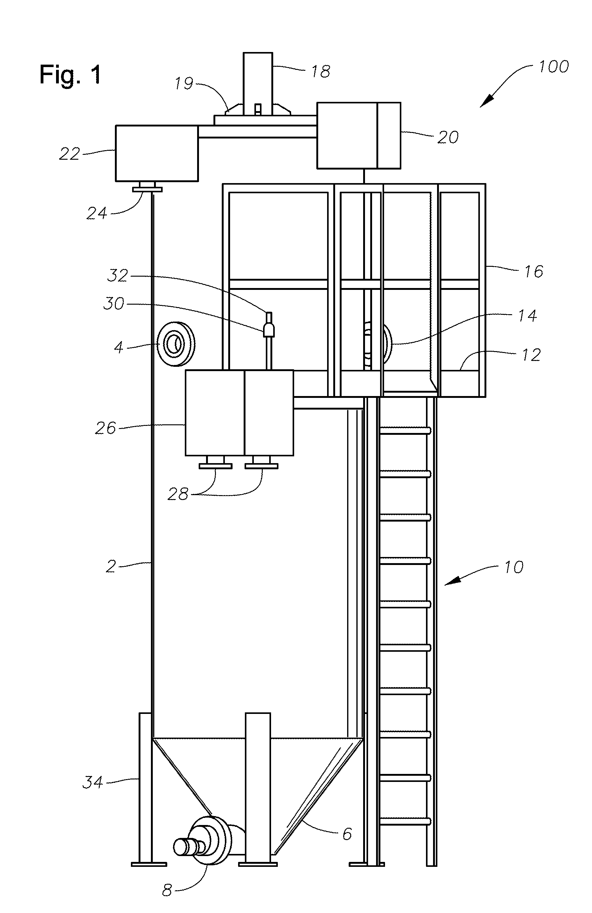
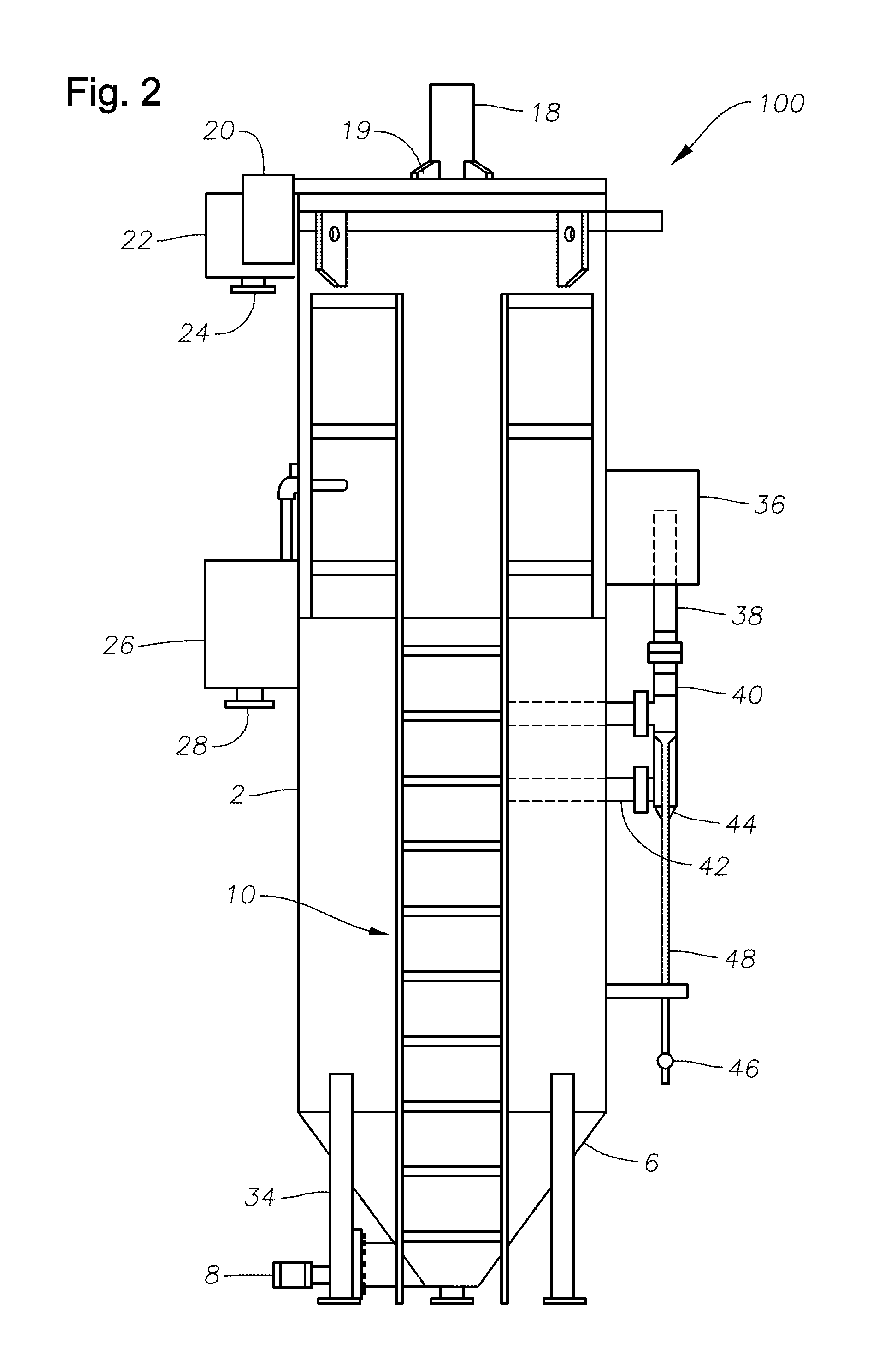
[0052]FIGS. 3 and 3A are schematic side elevation views, partially in cross-section, with parts broken away to illustrate certain internal features of filter apparatus embodiment 100 of FIGS. 1 and 2. Dual flexible couplings 50 fluidly connect effluent conduits 40, 42 to vessel 2, and include corresponding effluent valves 52. Vessel 2 contains a bed of granular filter media 3, and which is stratified as described herein. The filter media bed may have a double tapered conical shape and an unfiltered liquid descends downwardly through the filter media bed 3. Enhanced filtration is accomplished if the granule size of the filter media bed 3 is coarser, or larger at the outer area, becoming finer, or smaller toward the middle and center of the filter media bed 3.

[0053]The upper conical configuration 54 of filter media bed 3 occurs naturally from the operation of filtration apparatus embodiments described herein. As the filter media drops from washbox 18 onto the top of conical pile 54, t...

embodiment 200

[0059]FIGS. 6 and 6A are schematic side elevation views, partially in section, of certain external and internal features of a second filter embodiment in accordance with the present disclosure. In embodiment 200 of FIGS. 6 and 6A, deflector plate 71 is connected to the lower periphery of lower inverted cone 65 and slanted upward from a position near the inner surface of vessel 2 and extending toward but not touching that surface. Support brackets 80, 81 are provided, as well as a diverter plate 83, supported by a vertical plate 82. Vertical plate 82 prevents the hydraulic flow of fine grain sand and garnet to flow toward the center of the filter apparatus of the present disclosure.

[0060]The filtration process begins with the entry of the unfiltered liquid into vessel 2 through influent liquid connection 4. The unfiltered liquid descends, due to gravity, through the conical filter media bed 3, toward the bottom of the filter. The unfiltered liquid may be any liquid but will typically...

embodiment 300

[0069]In other embodiments of the present disclosure, the present liquid filtering apparatus may be used for “in-ground” installations, typically in new or existing concrete basins. This embodiment avoids the difficulty of piping the effluent out of the basin at a low level. This embodiment avoids designs that require the effluent to be removed via a pipe that exits through a side wall of the vessel. Such a design is particularly inconvenient in a poured concrete tank, especially if the concrete is an existing installation being converted to a vertical downflow moving bed sand filter. As illustrated in embodiment 300 of FIG. 7, this embodiment illustrates a concrete basin 302, and solves the effluent exit problem by bringing the effluent up through the center of a filter assembly 290 by means of concentric pipes, effluent riser pipe 238, and central pipe 220. The effluent passes upward and out of filter assembly 290 in effluent chamber 202, formed in the annulus between central pipe...


PUM

PropertyMeasurementUnit
granule sizeaaaaaaaaaa

Abstract

A liquid filtering apparatus is placed in a vessel having a bed of filtration material, the bed comprising at least two different sizes of filter media wherein the filtration material is stratified using upper and lower spaced apart inverted cones so that the unfiltered liquid first contacts coarse grained filtration material and then finer grained filtration material. The apparatus includes an intake for introducing unfiltered liquid that includes a washbox, an airlifting tube extending from the washbox and including an intake end and means for introducing a primary gas to the airlifting tube, the airlifting tube passing through a central pipe, which extends from just below the washbox to a position just above the intake end. The apparatus is devoid of screen cartridges. Methods of filtering and cleaning the filtration material are also disclosed.

Description

BACKGROUND[0001]1. Field of the Disclosure[0002]This disclosure relates to an apparatus and method for filtering liquids containing suspended solids. Specifically, this disclosure relates to an improved vertical filtration unit.[0003]2. Description of Related Art[0004]The removal of suspended solids from liquids, especially water, has been a longstanding requirement for many uses of such liquids. For example, water, which is free of suspended solids, is greatly preferred for uses, such as drinking, industrial processing, and swimming pools. Vertical filters, which utilize filter media, such as sand and garnet, have been used to separate suspended solids from water.[0005]Vertical filters operate by introducing the liquid containing suspended solids onto the top portion of a bed of filter media. As the liquid passes through the filter media under the force of gravity, the suspended solids adhere to the filter media and / or to solids accumulated on the filer media, allowing liquid essen...

Claims


Application Information

Patent Timeline
Patent Type & Authority Patents(United States)
IPC IPC(8): B01D24/46
CPCB01D24/10B01D24/4689
Inventor XIA, YONGMINGDEVINE, JEFFREY S.
Owner ALFA LAVAL ASHBROOK SIMON HARTELY INC
Learn More