Fuel cell

a fuel cell and fuel cell technology, applied in the field of fuel cells, can solve the problems of degrading performance and unable to discharge produced water from the fuel supply channel, and achieve the effect of simplifying the flow field structur

Active Publication Date: 2012-04-10
HONDA MOTOR CO LTD
View PDF9 Cites 0 Cited by
  • Summary
  • Abstract
  • Description
  • Claims
  • Application Information

AI Technical Summary

Benefits of technology

[0015]The present invention has been made to solve the above problem, and an object of the present invention is to provide a fuel cell having skip cooling structure in which the flow field structure is simplified, the water is discharged from the fuel cell smoothly, the gases are distributed smoothly, and the desired power generation performance of the fuel cell is maintained as a whole.
[0020]In the present invention, the first connection channel connecting the reactant gas passage and the first reactant gas flow field and the second connection channel connecting the reactant gas passage and the second reactant gas flow field include portions placed in the same plane formed by mutually facing the first and second separators. Therefore, the flow field structure is simplified effectively.
[0022]In the first connection channel and the second connection channel, flow distribution or merging from the reactant gas supply passage does not occur, and the pressure loss is suppressed. In this manner, it becomes possible to smoothly and reliably supply the reactant gas from the fuel gas supply passage to the first reactant gas flow field and the second reactant gas flow field.

Problems solved by technology

Therefore, the produced water cannot be discharged from the fuel supply channel 5b, and the performance may be degraded due to the insufficient stoichiometric ratio.

Method used


Image

  • Fuel cell
  • Fuel cell
  • Fuel cell

Examples


Embodiment Construction

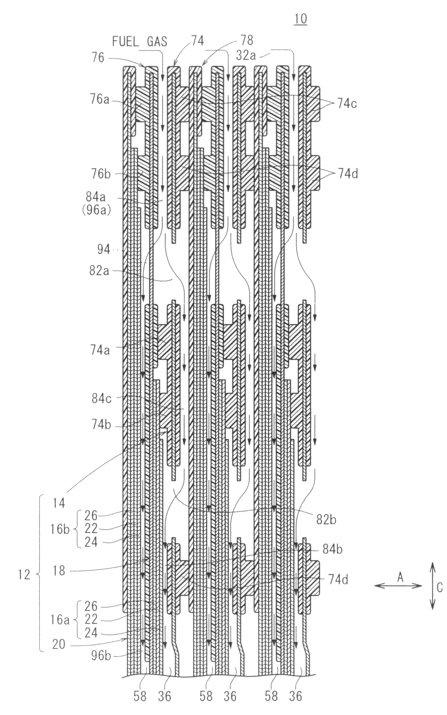
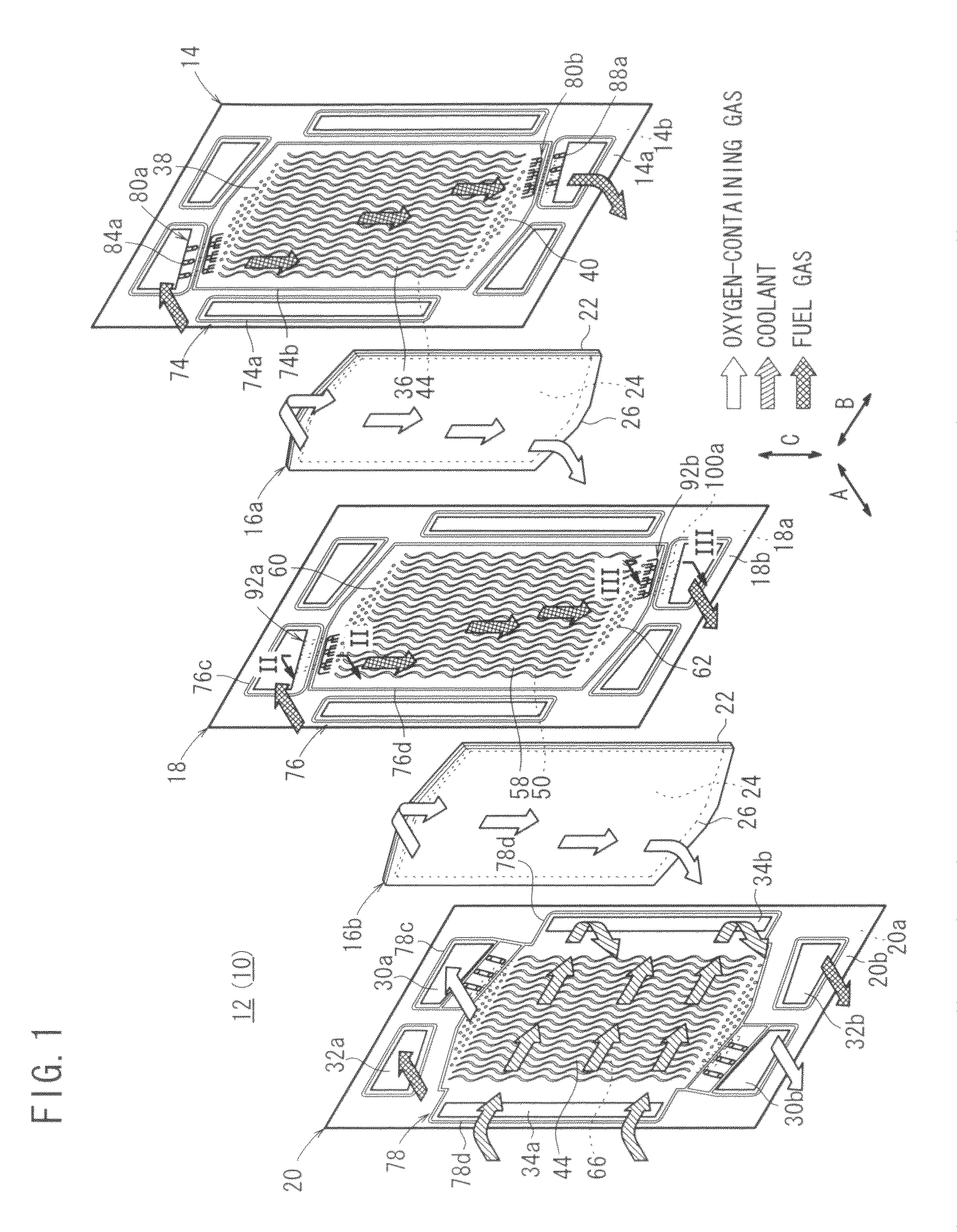
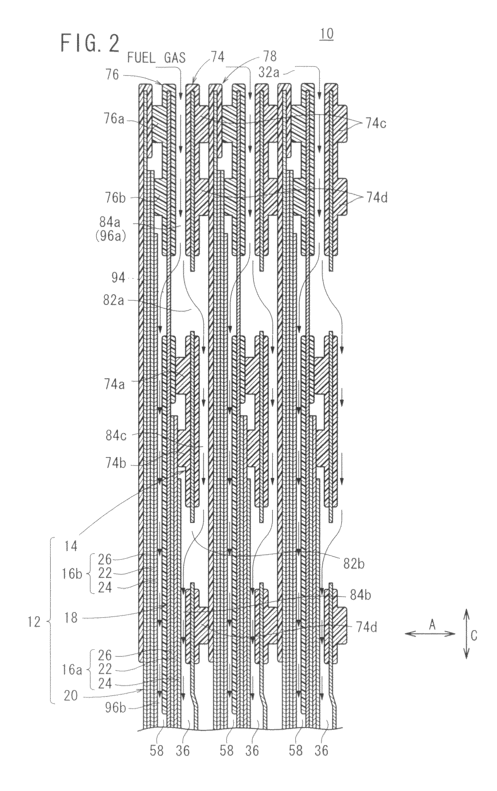
[0035]FIG. 1 is an exploded perspective view showing main components of a fuel cell 10 according to an embodiment of the present invention. FIG. 2 is a cross sectional view showing the fuel cell 10 taken along a line II-II in FIG. 1. FIG. 3 is a cross sectional view showing the fuel cell 10 taken along a line III-III in FIG. 1.

[0036]The fuel cell 10 is formed by stacking a plurality of power generation units 12 each including, in effect, two unit cells in a direction indicated by an arrow A. Each of the power generation unit 12 includes a first separator 14, a first membrane electrode assembly (electrolyte electrode assembly) 16a, a second separator 18, a second membrane electrode assembly 16b, and a third separator 20. The power generation unit 12 may include three or more unit cells.

[0037]For example, the first separator 14, the second separator 18, and the third separator 20 are steel plates, stainless steel plates, aluminum plates, plated steel sheets, or metal plates subjected ...


PUM

PropertyMeasurementUnit
lengthaaaaaaaaaa
weightaaaaaaaaaa
power generation performanceaaaaaaaaaa

Abstract

A first separator has an outlet side first connection channel connecting a first fuel gas flow field and a fuel gas discharge passage, and a second separator includes an outlet side second connection channel connecting a second fuel gas flow field and the fuel gas discharge passage. The outlet side first connection channel and the outlet side second connection channel include outer passages and outer passages arranged in the same plane formed by facing the first separator and the second separator. The outer passages and the outer passages are formed alternately and independently in the same plane.

Description

BACKGROUND OF THE INVENTION[0001]1. Field of the Invention[0002]The present invention relates to a fuel cell formed by stacking a plurality of power generation units. Each of the power generation units comprises first and second electrolyte electrode assemblies, and is formed by stacking the first electrolyte electrode assembly on a first separator, a second separator on the first electrolyte electrode assembly, the second electrolyte electrode assembly on the second separator, and a third separator on the second electrolyte electrode assembly. Each of the first and second electrolyte electrode assemblies includes a pair of electrodes and an electrolyte interposed between the electrodes. A reactant gas passage for at least a fuel gas or an oxygen-containing gas as one of reactant gases extends through the power generation units, and a coolant flow field for a coolant is formed between the power generation units.[0003]2. Description of the Related Art[0004]For example, a solid polyme...

Claims


Application Information

Patent Timeline
Patent Type & Authority Patents(United States)
IPC IPC(8): H01M8/04
CPCH01M8/0202H01M8/04089H01M8/04156H01M8/0263H01M8/0267H01M8/242H01M2008/1095Y02E60/50H01M8/2483H01M8/2457H01M8/0258H01M8/241
Inventor ODA, MASARUCHIBA, HIROTOMOHRI, MASAHIROIWASAWA, CHIKARASUGITA, NARUTOSHI
Owner HONDA MOTOR CO LTD
Why Eureka
Try Eureka