Method of improving the efficiency of loosely packed solar cells in dense array applications

Inactive Publication Date: 2012-04-10
ARZON SOLAR LLC
View PDF33 Cites 17 Cited by
  • Summary
  • Abstract
  • Description
  • Claims
  • Application Information

AI Technical Summary

Benefits of technology

[0008]The principle object of the present invention is to provide a method for utilization of the light falling between active areas of loosely packed solar cells. Secondarily, this invention provides protection from highly concentrated sunlight to the areas between cells, to permit these areas to act as protective enclosures for interconnecting wiring, and discrete diodes. This invention is comprised of a matrix of reflective surfaces interconnected tent fashion, over the intercellular areas of the substrate. These reflective surfaces reflect the sunlight, or a portion thereof, back to the active areas of the solar cells. They may be oriented symmetrical about an axis normal to the substrate or skewed to accommodate a conical beam of concentrated sunlight, as from a circular paraboli

Problems solved by technology

Furthermore the entire front surface area of the cell may not be active due to the necessity of a front surface contact to which the ribbons are bonded.
Excessive spacing might lead to a slightly higher manufacturing cost due to a larger than necessary substrate, and a marginally lower system efficiency, but from a practical standpoint packing density is not a major concern for one sun solar panels.
Concentr

Method used


Image

  • Method of improving the efficiency of loosely packed solar cells in dense array applications
  • Method of improving the efficiency of loosely packed solar cells in dense array applications
  • Method of improving the efficiency of loosely packed solar cells in dense array applications

Examples


Embodiment Construction

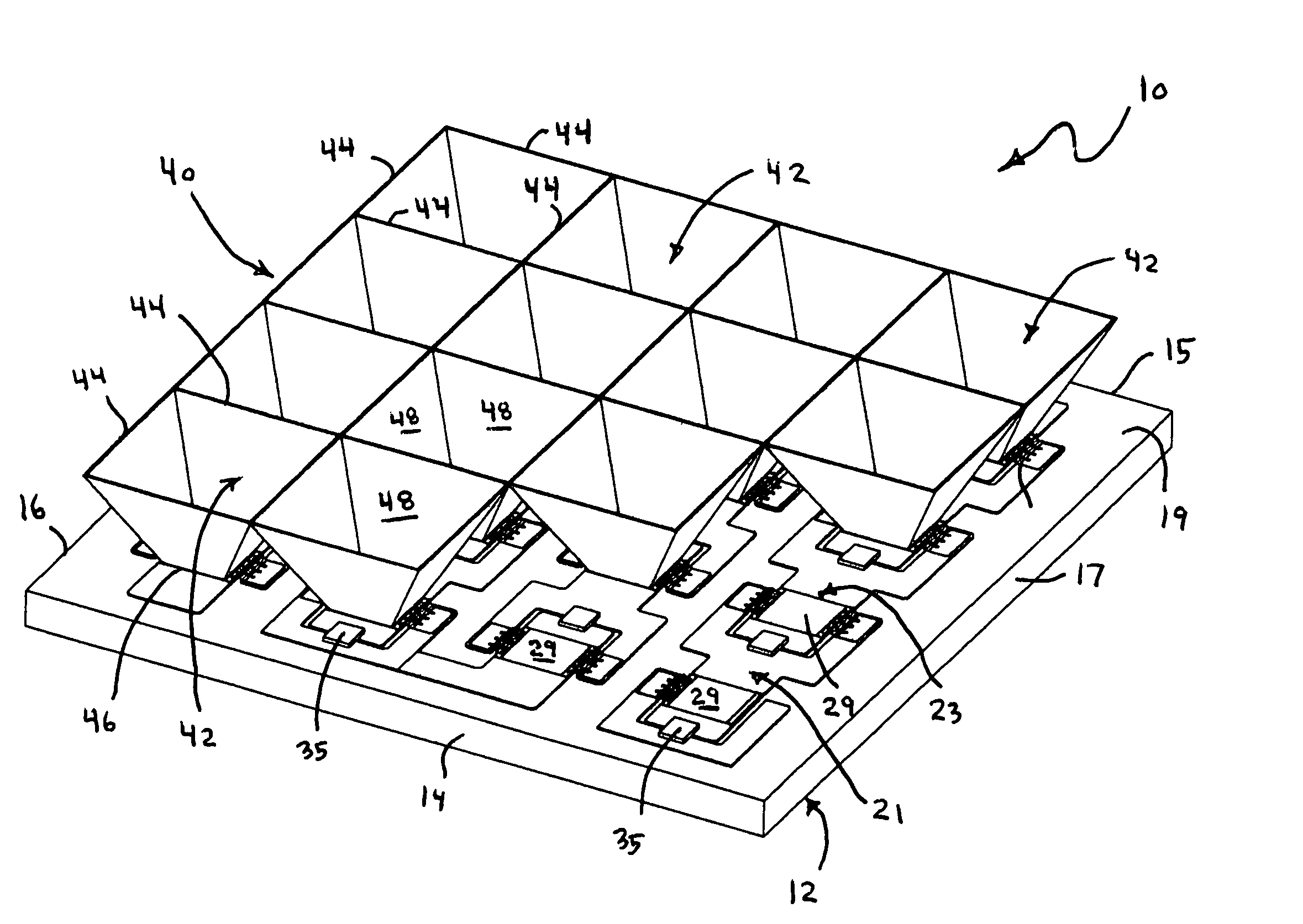
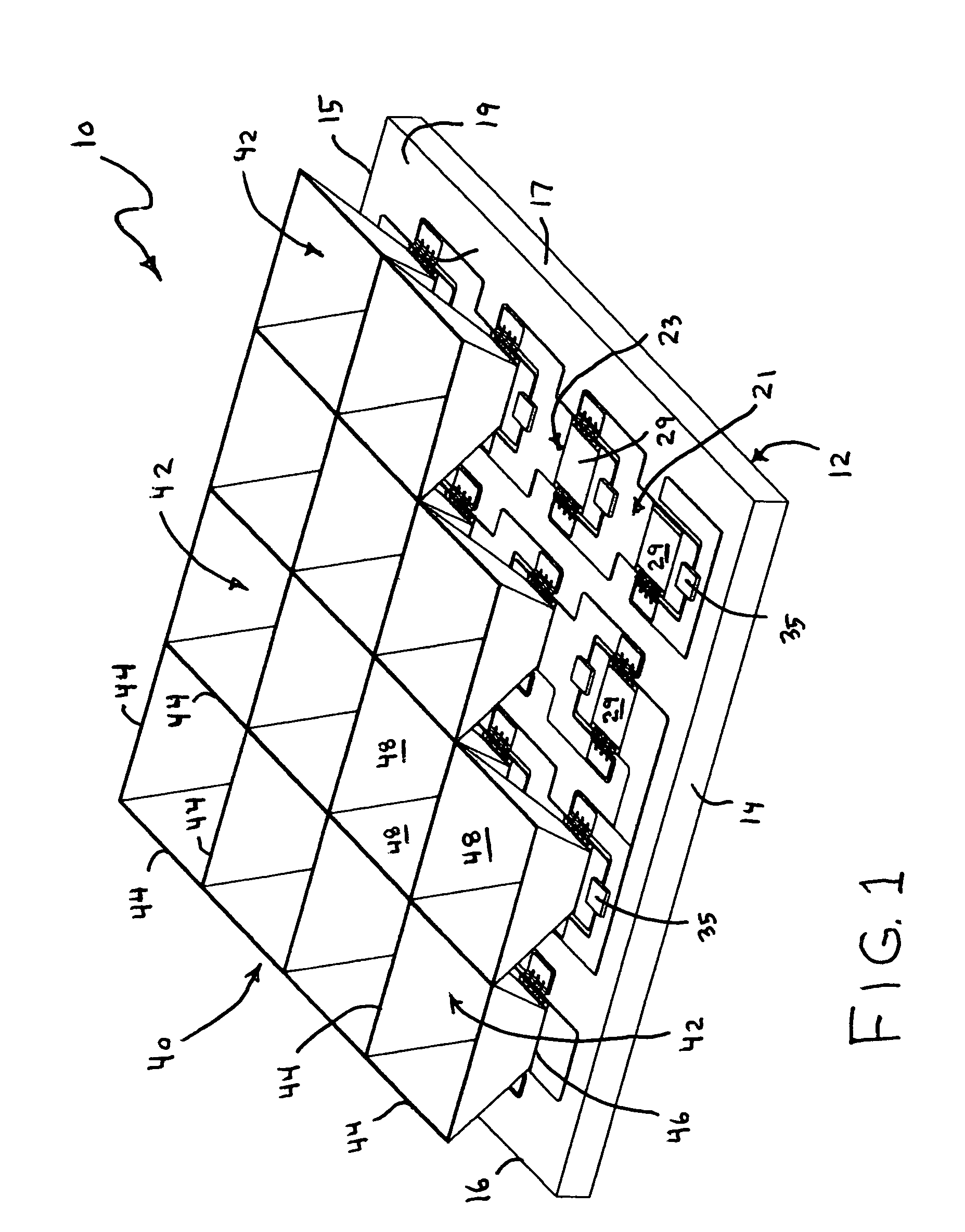
[0012]The increased efficiency Concentrator Photovoltaic (PV) System will now be described by referring to FIGS. 1 and 2 of the drawings. The PV System is generally designated numeral 10. It has a substrate 12 having a front end 14, a rear end 15, a left end 16, a right end 17 and a top surface 19. Substrate 12 may be made of a non-electrical conducting material or a conducting material such as metal in which the top surface has been rendered non-conductive by application of a surface treatment or coating on the non-conductive material.

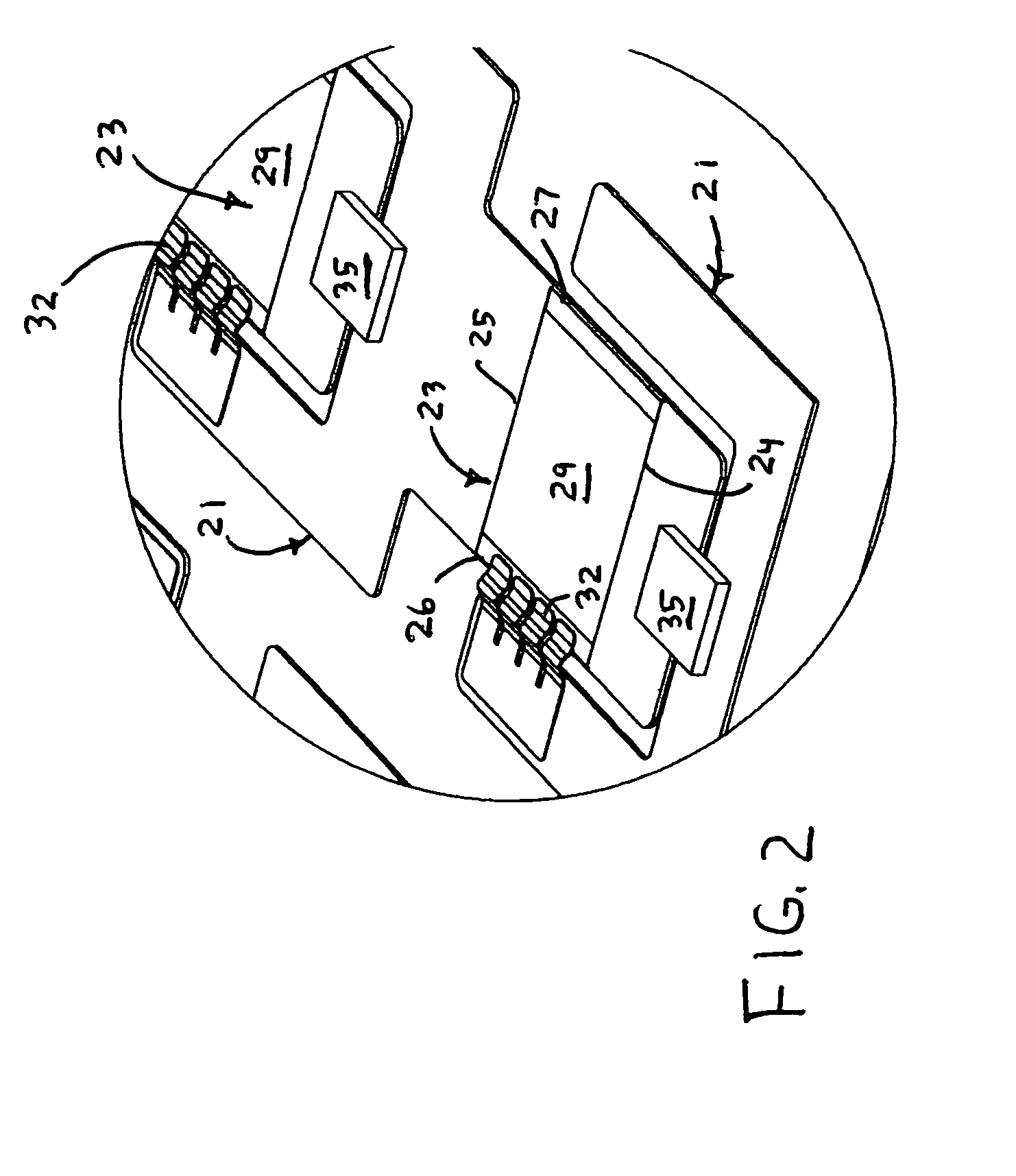
[0013]A plurality of metal traces 21 are located on top surface 19 and they provide a surface upon which the solar cells 23 can be supported and also provide a path for the electrical output of the individual solar cells 23. The solar cells 23 have a front edge 24, a rear edge 25, a left edge 26, a right edge 27 and a top surface 29. Top surface 29 is the active area that receives the solar rays that produce electricity. Metal ribbons / wires 32 provide...


PUM


Abstract

An increased efficiency Concentrator Photovoltaic System having a plurality of solar cells laterally spaced from each other on a substrate panel. The solar cells are mounted on electrically conductive areas of an otherwise non-conductive top surface of the substrate with each cell isolated from another by a non-conductive area. The individual cells are connected using ribbons or wires, between the front contact of the solar cells to the conductive area of another cell to form a circuit connecting the cells in a desired configuration. A plurality of tubular enclosures for concentrating light on the solar cells are mounted directly above the solar cells.

Description

[0001]This patent application claims the priority date of U.S. Provisional Patent Application No. 60 / 512,888 filed Oct. 20, 2003.BACKGROUND OF THE INVENTION[0002]1. Field of the Invention[0003]The present invention relates to the assembly of solar cells into an array for the conversion of solar energy from a large area concentrator, typically a parabolic reflector or the optical equivalent constructed of mirror segments, either flat or figured, into electricity. More specifically it applies to the methodology of maximizing the fraction of sunlight captured by the concentrator that is converted into electrical power.[0004]2. Prior Art[0005]Traditional one sun solar panels are made by simply bonding solar cells to a substrate, such as aluminum honeycomb panels, and interconnecting the cells with metal ribbons front to back. The cells are spaced slightly apart to allow the interconnecting ribbons to pass between the adjacent cells. Furthermore the entire front surface area of the cell ...

Claims


Application Information

Patent Timeline
IPC IPC(8): H01L31/045H02S30/20
CPCH01L31/0504H01L31/0547H01L31/0508Y02E10/52Y10S136/293
Inventor GARBOUSHIAN, VAHANSLADE, ALEXANDER M.
Owner ARZON SOLAR LLC
Why Eureka
Try Eureka