Compact self-contained condition monitoring device

a condition monitoring and compact technology, applied in the direction of motor/generator/converter stopper, dynamo-electric converter control, instruments, etc., can solve the problems of tens of thousands of dollars, expensive rotating equipment with monitors attached for continuous monitoring, and high cost of vibration monitoring equipment, etc., to achieve compact configuration and low cost. , the effect of low cos

Active Publication Date: 2012-04-10
ITT MFG ENTERPRISES LLC
View PDF24 Cites 38 Cited by
  • Summary
  • Abstract
  • Description
  • Claims
  • Application Information

AI Technical Summary

Benefits of technology

[0014]According to some embodiments of the present invention, the disposable, compact, self-contained, battery operated, warning and alarming condition monitoring device may be affixed or mounted on the second device, e.g. affixed on a bearing frame of the pump.
[0020]In effect, the present invention provides a novel and unique method and apparatus for monitoring vibration in a very low cost, compact configuration. This makes it economical to provide continuous monitoring on every pump or piece of rotating equipment in a chemical plant. The condition monitor may employ low cost Microelectromechanical system (MEMS) developed for the automotive industry, very low electrical power microprocessors, and the latest battery technology combined into a novel and economical device that provides early warning of equipment problems. The present invention brings down the cost of continuous monitoring equipment from tens of thousands of dollars to a few hundred dollars. The low cost makes it possible to mount this invention on every rotating machine in a plant and have the benefits of continuous monitoring without the prohibitive high cost. The low electrical power requirements allows for battery operation with long life. This allows for a small self contained sealed unit with no external wiring and a simple mechanical screw attachment to the equipment to be monitored.
[0021]The vast majority of rotating equipment and in particular centrifugal pumps rotate between 600 and 3600 revolutions per minute (rpm). The measure of vibration most useful in diagnosing equipment in this typical speed range is the measurement of velocity. The invention uses a circuit to convert the electrical output from the Microelectromechanical system (MEMS) to a voltage that is proportional to the vibration velocity of the pump. The vibration of the equipment measured as velocity is used universally to assess the machine condition. In addition to the low cost, the invention provides simple setup and operation with no special analysis skills required to determine equipment condition. The device does not require a trained equipment expert to interpret the equipment condition. Any person walking by the pump can immediately determine the pump condition by visual observation of the light emitting diodes on the monitor (green flashing OK, red flash alarm). This visual observation is not limited to light emitting diodes. Other embodiments for the visual observation can be a LCD display or other visual means. Setting the alarm level is as simple as turning the monitor on. The first function performed when the monitor is activated is to capture the current vibration level and use that baseline level to set the alarm vibration level. The alarm level is stored in the microprocessor's memory. Subsequent vibration level measurements are compared to the alarm level and the machine status is annunciated. The vibration alarm level is unique to the machine and operating conditions of the installation. The alarm level is not determined, but is uniquely determined at startup based on the particular installation.

Problems solved by technology

Vibration monitoring equipment can be expensive, in the tens of thousands of dollars.
As such, only very expensive rotating equipment have monitors attached for continuous monitoring.
For 99% of the rotating equipment that cannot justify the expense of continuous vibration monitoring, either, no vibration measurement is employed or a walk around vibration program is used employing expensive portable vibration equipment and manual labor expense.
Pump health can change between walk-arounds due to system upsets and / or operator error.
This type of manual system does not provide continuous monitoring and as such does not optimize preventive maintenance.

Method used


Image

  • Compact self-contained condition monitoring device
  • Compact self-contained condition monitoring device
  • Compact self-contained condition monitoring device

Examples


Embodiment Construction
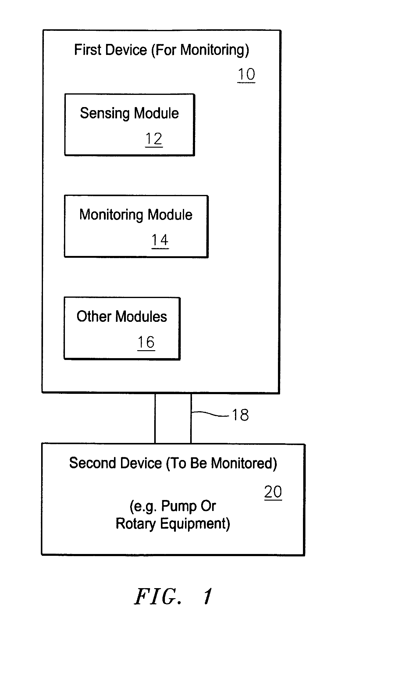
FIG. 1

The Basic Invention

[0031]FIG. 1 shows the basic invention in the form of a first device 10 that monitors the operation of a second device 20, such as a pump, a fan, compressor, turbine or other rotating or reciprocating piece of machinery. As shown, the first device 10 may be affixed or mounted on the second device 20, e.g. the first device 10 may be affixed via some affixing member 18 on a bearing frame (not shown) of the second device 20, such as a pump. The first device 10 is designed to be a disposable, compact, self-contained, inexpensive, battery operated, warning and alarming condition monitoring device. The affixing member 18 may take the form of glue, epoxy, fasteners, etc., and the scope of the invention is not intended to be limited to any particular type or kind of affixing member either now known or later developed in the future, or the overall manner in which the first and second devices are coupled together.

[0032]The first device 10 includes a sensing module 12,...


PUM


Abstract

The present invention provides a new and unique method and apparatus for monitoring a device, such as a pump. The device may also include a fan, compressor, turbine or other rotating or reciprocating piece of machinery. In one embodiment, the method features sensing in a first device both a start-up vibration at a start-up time after the first device is affixed to a second device to be monitored and a subsequent vibration level at a subsequent time after the start-up time, and providing both a start-up vibration level signal containing information about the start-up vibration level of the second device, and a subsequent vibration level signal containing information about the subsequent vibration level of the second device; and monitoring in the first device the condition of operation of the second device based on a comparison of the start-up vibration level signal in relation to the subsequent vibration level signal. The apparatus may take the form of one or more modules and / or chipset for performing the steps and functionality of the aforementioned method.

Description

CROSS-REFERENCE TO RELATED APPLICATIONS[0001]This application claims benefit to provisional patent application No. 60 / 997,911, filed 5 Oct. 2007, which is hereby incorporated in its entirety be reference.BACKGROUND OF THE INVENTION[0002]1. Field of the Invention[0003]The present invention relates to a method and apparatus for a first device to monitor the operation of a second device, including the monitoring of a pump, a fan, compressor, turbine or other rotating or reciprocating piece of machinery; and more particularly related to a disposable, compact, self-contained, battery operated, warning and alarming condition monitoring device for monitoring a pump.[0004]2. Brief Description of Related Art[0005]Temperature and vibration monitoring of rotation equipment is a known and accepted method to determining the health of rotating equipment.[0006]Temperature measurement of equipment as a diagnostic tool is simple and relatively inexpensive to implement. Temperature information is use...

Claims


Application Information

Patent Timeline
Patent Type & Authority Patents(United States)
IPC IPC(8): G08B21/00
CPCG01H1/003
Inventor HAUENSTEIN, KENNETH LEEPADDOCK, DOUGLASPLAYFORD, MARK ALEXANDERQUILL, JERMIAH DENNISRICE, DAVID A.BRUSA, PATRICK J.
Owner ITT MFG ENTERPRISES LLC
Why Eureka
Try Eureka