Object detection

a technology for objects and detection methods, applied in the field of objects detection, can solve problems such as inability to assign a distinct pulse train to each individual

Active Publication Date: 2012-04-10
MITSUBISHI ELECTRIC R&D CENTRE EUROPE BV
View PDF23 Cites 78 Cited by
  • Summary
  • Abstract
  • Description
  • Claims
  • Application Information

AI Technical Summary

Benefits of technology

[0017]Using such a technique, it is possible to provide an improved method for encoding pseudorandom binary sequences to obtain a plurality of pulse trains intended for ranging applications.

Problems solved by technology

However, because it is not possible to predict which of the many similar systems will be operating in a particular region, it is not practical to assign a distinct pulse train to each of them.

Method used


Image

  • Object detection
  • Object detection
  • Object detection

Examples


example 1

[0071]Assume that the number J of clock pulses occurring in a single cycle is equal to 30, and that the minimum and maximum values of the interpulse interval are, respectively, Tmin=40 ns and Tmax=185 ns. Because each value of the interpulse interval is to occur exactly once, the histogram of the interval values will be of the form shown in FIG. 6. As seen, the durations of the interpulse intervals increase in steps of 5 ns.

[0072]In this case, the average value of the interpulse interval is equal to 112.5 ns, but may easily be varied, e.g. by changing the minimum value Tmin of the interpulse interval. This can be accomplished by applying a suitable signal to input AS of the spread-period clock generator.

[0073]While the order in which different interpulse interval values occur cannot change the histogram shape, it does make the resulting series of antithetic clicks statistically distinct, especially when the permutation of interval values is carried out repeatedly, e.g., on a cycle-t...

example

[0083]Assume that K=6, −NV=−4 and Tc=5 ns.

[0084]Therefore, Tmin=(NV)Tc=20 ns, whereas Tmax=Tmin+(2K−1)Tc=215 ns.

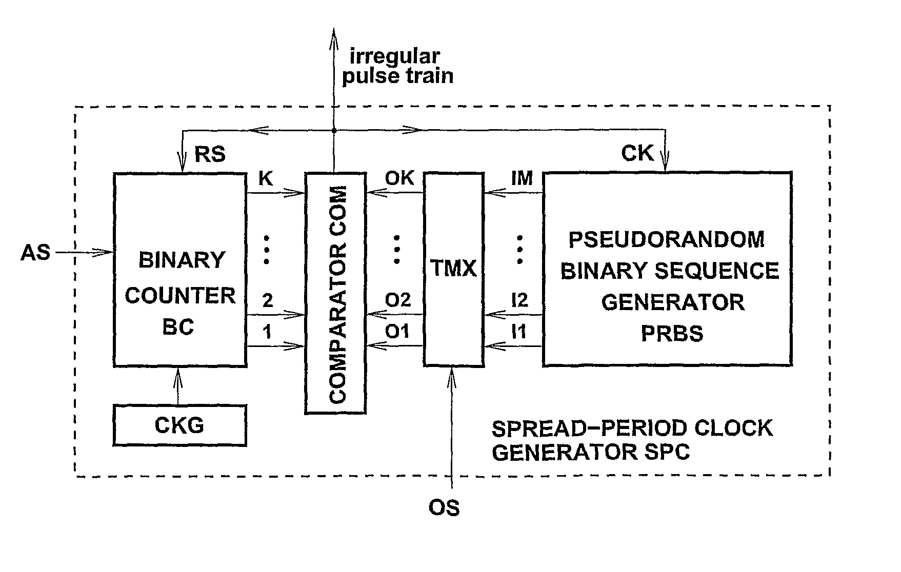
[0085]In a general case, the transition-matrix circuit TMX has M inputs and K outputs, where M≧K. However, in the simplest arrangement, M=K, and the TMX has K inputs, I1, I2, . . . , IK and K outputs, O1, O2, . . . , OK; hence the PRBS generator has K parallel outputs driving inputs I1, I2, . . . , IK. The operation of the TMX can be explained by way of an example shown in FIG. 17. The pattern of K, K=8, dots in a K×K matrix corresponds to input-output connections realized by the TMX. Therefore, in this case, O1=I7, O2=I1, . . . , O7=I2 and O8=I5. Obviously, each column and each row of the matrix must contain exactly one dot.

[0086]Although many different dot patterns can be devised for this application, it may be advantageous to utilize a dot pattern belonging to a class of patterns referred to as ‘K non-attacking Queens’, such as the dot pattern shown in FIG. 17. Also, ot...

example 2

[0121]Assume that the template binary waveform b(t) is a ‘maximal-length’ pseudorandom binary signal generated by a seven-stage shift register as shown in FIG. 9. Therefore, the duration of each prbs period will be equal to 127 clock interpulse intervals.

[0122]Assume also that the prbs generator is driven by a spread-period clock generator that operates cyclically, and its characteristics are the same as those discussed in Example 1, namely:[0123]1. the number K of clock pulses occurring in a single cycle is equal to 30;[0124]2. the minimum and maximum values of the interpulse interval are, respectively, Tmin=40 ns and Tmax=185 ns, with the average value of 112.5 ns,[0125]3. the duration of the interpulse intervals always increases by a step of 5 ns.

[0126]When clock pulses with the above characteristics drive the prbs generator, the output compound binary waveform will repeat itself every 127×30=3810 clock interpulse intervals, or 3810×112.5 ns≈429 μs (this is because 127 and 30 are...


PUM


Abstract

An object is detected by generating a m-ary primary signal having an irregular sequence of states. Each transition results in the transmission of a pulse encoded according to the type of transition. Reflected pulses are processed with a delayed, reference version of the primary signal. The presence of an object at a range corresponding to the delay is determined from the extent to which the reflected pulses coincide with transitions in the reference signal. In one aspect, transitions between states of the primary signal occur at varying time offsets with respect to nominal regular clock pulses. In another aspect, the object-detection system is operated while inhibiting the transmission of pulses, and if a significant output is obtained, the parameters of the transmitted signal are altered.

Description

BACKGROUND OF THE INVENTION[0001]1. Field of the Invention[0002]This invention relates to a method and apparatus for the generation and processing of trains of pulses, for example to be utilized as interrogating waveforms in object detection systems such as multi-user active sensor systems and particularly, but not exclusively, in automotive radar systems designed to perform functions of obstacle-detection and / or collision-avoidance.[0003]2. Description of the Prior Art[0004]One important type of obstacle-detection / collision-avoidance automotive systems employs short pulses of electromagnetic energy to interrogate the detection zone of interest. A decision regarding the presence or absence of an obstacle at a predetermined range is then made by suitably processing energy backscattered by various objects in the field of view of the system.[0005]FIG. 1 is a block diagram of a conventional obstacle-detection system utilizing short pulses of electromagnetic energy. The system comprises ...

Claims


Application Information

Patent Timeline
Patent Type & Authority Patents(United States)
IPC IPC(8): G01S13/00G01S13/08
CPCG01S13/106
Inventor SZAJNOWSKI, WIESLAW JERZY
Owner MITSUBISHI ELECTRIC R&D CENTRE EUROPE BV
Why Eureka
Try Eureka