Composite truss armor

a composite armor and micro-truss technology, applied in the direction of protective equipment, weapons, instruments, etc., can solve the problems of reducing the maximum size of plates a soldier can carry, and leaving unprotected areas on the soldier's body

Active Publication Date: 2012-04-10
HRL LAB
View PDF31 Cites 24 Cited by
  • Summary
  • Abstract
  • Description
  • Claims
  • Application Information

AI Technical Summary

Benefits of technology

[0031]In one embodiment, the three-dimensional ordered truss structure and the armor filler material include ceramic and metallic material componen

Problems solved by technology

However, these vests are incapable of defeating the ballistic threats imposed by military pattern rifles firing high-velocity, armor-piercing (AP) projectiles.
(1) Weight: Soldiers are often overburdened by the additional weight of these plates, and are forced to forgo the additional protection in order to carry other gear. Additionally, the weight reduces the maximum size of the plates a soldier can carry and leaves unprotected areas on a soldier's body.
(2) Bulk: The bulkiness of the plate inserts makes them visible to the enemy, allowing enemy soldiers to shoot around the plates hitting more vulnerable areas.
(3) Overheating: The heat trapping properties of trauma plates make them uncomfortable to wear in hot, desert climates. Therefore, the existence of a lightweight, lower profile, breathable Level IV trauma plate would be of great interest to the US armed forces.
(4) Thermal attack: Ceramic armor plates are not designed to defend against thermal or directed energy attacks. The two (2)-dimensional nature of the current laminated construction provides poor thermal conductivity, allowing hot

Method used


Image

  • Composite truss armor
  • Composite truss armor
  • Composite truss armor

Examples


Embodiment Construction

[0055]In the following detailed description, only certain exemplary embodiments of the present invention are shown and described, by way of illustration. As those skilled in the art would recognize, the described exemplary embodiments may be modified in various ways, all without departing from the spirit or scope of the present invention. Accordingly, the drawings and description are to be regarded as illustrative in nature, and not restrictive.

[0056]In the context of embodiments of the present invention, a three-dimensional ordered microstructure is referred to as an ordered three-dimensional structure having order at the micrometer scale.

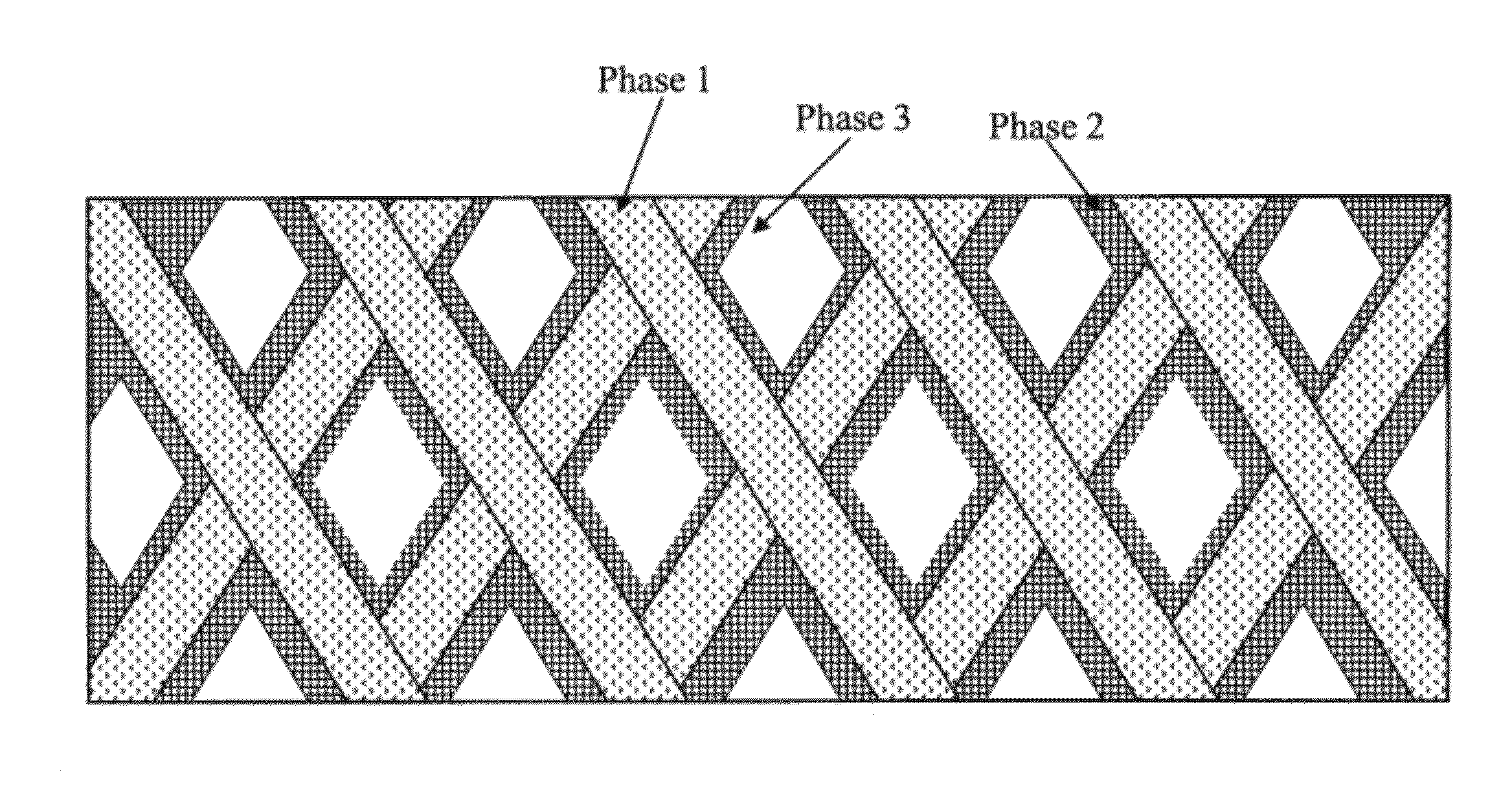
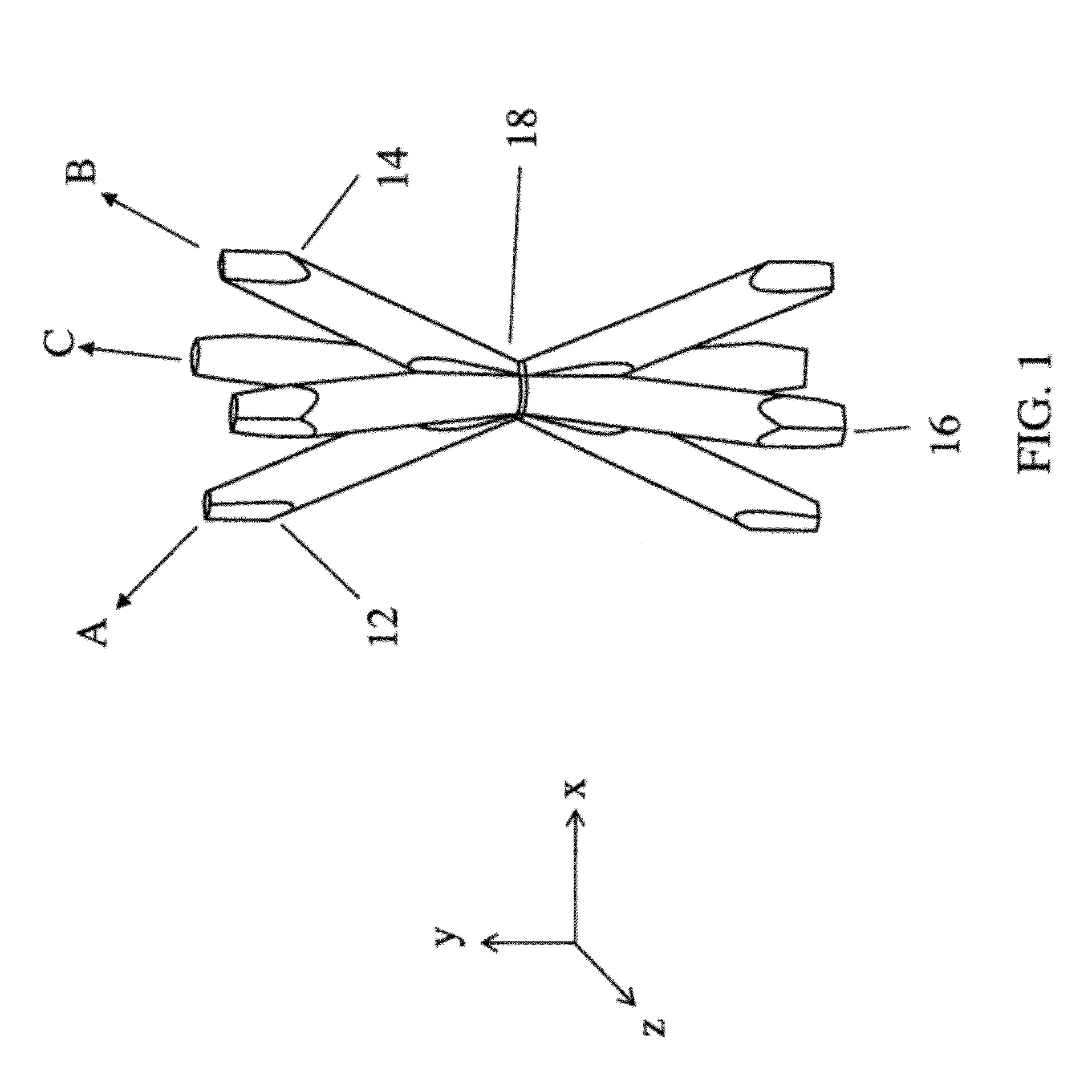
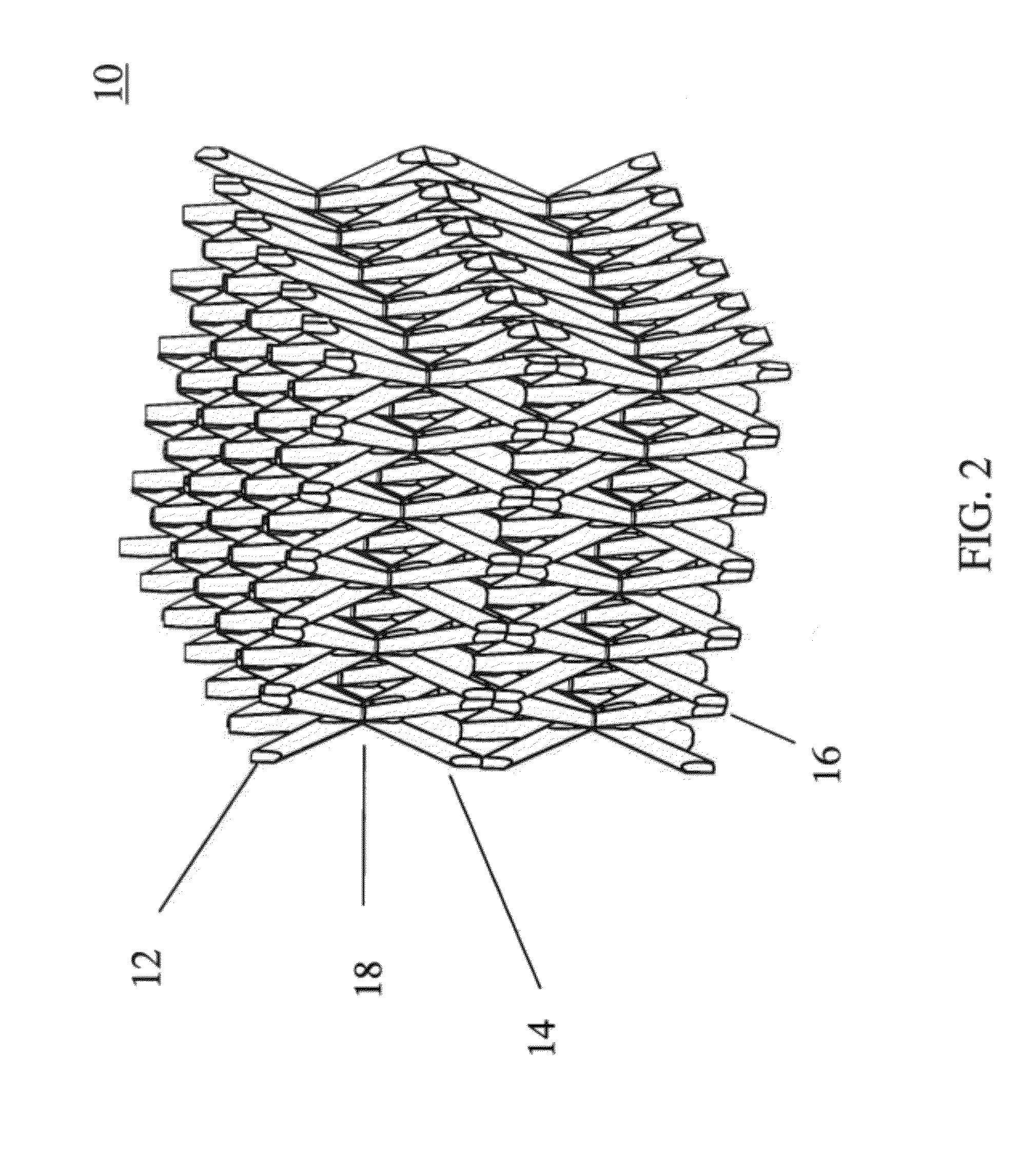
[0057]An embodiment of the present invention provides a method and / or system of fabricating armor from small scale 3-dimensionally ordered truss structure. An armor according to an embodiment of the present invention incorporates ceramic and metallic continuous phases, interwoven and repeating with both long range and short range order. To put it ...


PUM


Abstract

A composite truss armor and a method of manufacturing the same. The composite truss armor includes a filler material and a three-dimensional (3D) ordered truss structure. The 3D ordered truss structure includes: a plurality of first truss elements defined by a plurality of first self-propagating polymer waveguides and extending along a first direction; a plurality of second truss elements defined by a plurality of second self-propagating polymer waveguides and extending along a second direction; and a plurality of third truss elements defined by a plurality of third self-propagating polymer waveguides and extending along a third direction. The first, second, and third ordered truss elements interpenetrate each other at a plurality of nodes to form a continuous material. The first, second, and third truss elements define an open space. The filler material occupies at least a portion of the open space, and the 3D ordered truss structure is self-supporting.

Description

FIELD OF THE INVENTION[0001]The present invention relates to a micro-truss based composite armor (or composite truss armor) and a method and / or system of manufacturing the same.BACKGROUND OF THE INVENTION[0002]Standard flexible body armors (a.k.a. “bullet proof” vests) are commonly used by police officers throughout the United States. However, these vests are incapable of defeating the ballistic threats imposed by military pattern rifles firing high-velocity, armor-piercing (AP) projectiles. As these threats are frequently encountered during wartime, the US military has adopted body armor with pockets which can accommodate hard ballistic trauma plate inserts, which can defeat AP rifle fire. The National Institute of Justice (NIJ) classifies AP rifle fire as threat level IV, and any ballistic armor plate certified to defeat a level IV threat must be capable of stopping projectiles up to and including AP 7.62×63 mm (30-06). Current state of the art level IV trauma plates are manufactu...

Claims


Application Information

Patent Timeline
IPC IPC(8): G02B6/00
CPCF41H5/0414F41H5/0442F41H5/0492
Inventor CUMBERLAND, ROBERT W.JACOBSEN, ALAN J.GROSS, ADAM F.
Owner HRL LAB
Why Eureka
Try Eureka