Underground storage tank with sediment trap

a technology of sediment traps and storage tanks, applied in liquid handling, packaging goods types, transportation and packaging, etc., can solve the problems of owners of usts incurring remediation costs, damage to tank systems such as valves, valves, sensors, etc., and achieve the effect of preventing contamination

Inactive Publication Date: 2012-04-17
J D STEIN
View PDF25 Cites 1 Cited by
  • Summary
  • Abstract
  • Description
  • Claims
  • Application Information

AI Technical Summary

Benefits of technology

[0014]The trap inside wall and the tank sump perimeter wall are in spaced-apart relation, which may be annular. A annular space is defined by the trap inside wall and the sump perimeter wall. A drainage medium, as defined above, is disposed within the annular space and is in fluid communication with the drainage medium surrounding the underground storage tank. The voids between the individual pieces of the drainage medium allow water to flow readily through the drainage medium and away from the underground storage tank.
[0018]An operator maintains the sediment trap and water drainage system by removing accumulated sediment from the bottom of the interior volume of the trap. Because the sediment and debris in the water entering the drainage medium is substantially reduced, blinding of the drainage medium by sediment and debris is slowed and the life of the drainage medium is extended. Because the top of the trap interior volume is open and due to the shape of the sediment trap, the sediment may be readily removed by the operator, as by use of a familiar shop vacuum cleaner.
[0022]The bottom of the annular space between the trap inside wall and the tank sump perimeter wall may be sealed. If the bottom of the annular space is sealed, the annular space interior volume is water and liquid-tight. The annular space interior volume then defines a second sediment trap and also defines a secondary containment for liquid, such as a petroleum product, that may be released from the tank sump. For example, a leak or spill of a petroleum product within the tank sump may fill the tank sump and overtop the sump perimeter wall and the petroleum product then would flow into the secondary containment. The secondary containment defined by the Liquid-tight annular space interior volume prevents liquid that escapes from the tank sump from being released into the environment, preventing contamination and preventing the owner of the tank from incurring the costs of remediation of the environmental contamination.
[0023]The second sediment trap and secondary containment may be drained by an annular space drainage pipe in fluid communication with the annular space interior volume at an elevation above the bottom of the annular space. Sealing the bottom of the annular space and Locating the annular space drainage pipe above the elevation of the bottom of the annular space allows the second sediment trap to store water and allows additional sediment to settle from the water. Locating the annular space drainage pipe above the elevation of the sealed bottom of the annular space also allows the annular space interior volume to store petroleum or other liquid that escapes from the tank sump, providing the secondary containment for the tank sump.

Problems solved by technology

The problem addressed by the Invention is the flooding of electrical pumps and other subterranean systems serving underground storage tanks due to the blinding of underground water drainage systems by sediment and debris.
If the liquid escapes from the tank sump, as by overflowing the tank sump perimeter wall, the liquid is released into the environment, causing environmental damage and causing the owner of the UST to incur remediation costs.
The failure of this drainage system allows the tank sump to flood, damaging tank systems such as electrical pumps, sensors, valves, piping or related systems.

Method used


Image

  • Underground storage tank with sediment trap
  • Underground storage tank with sediment trap
  • Underground storage tank with sediment trap

Examples


Embodiment Construction

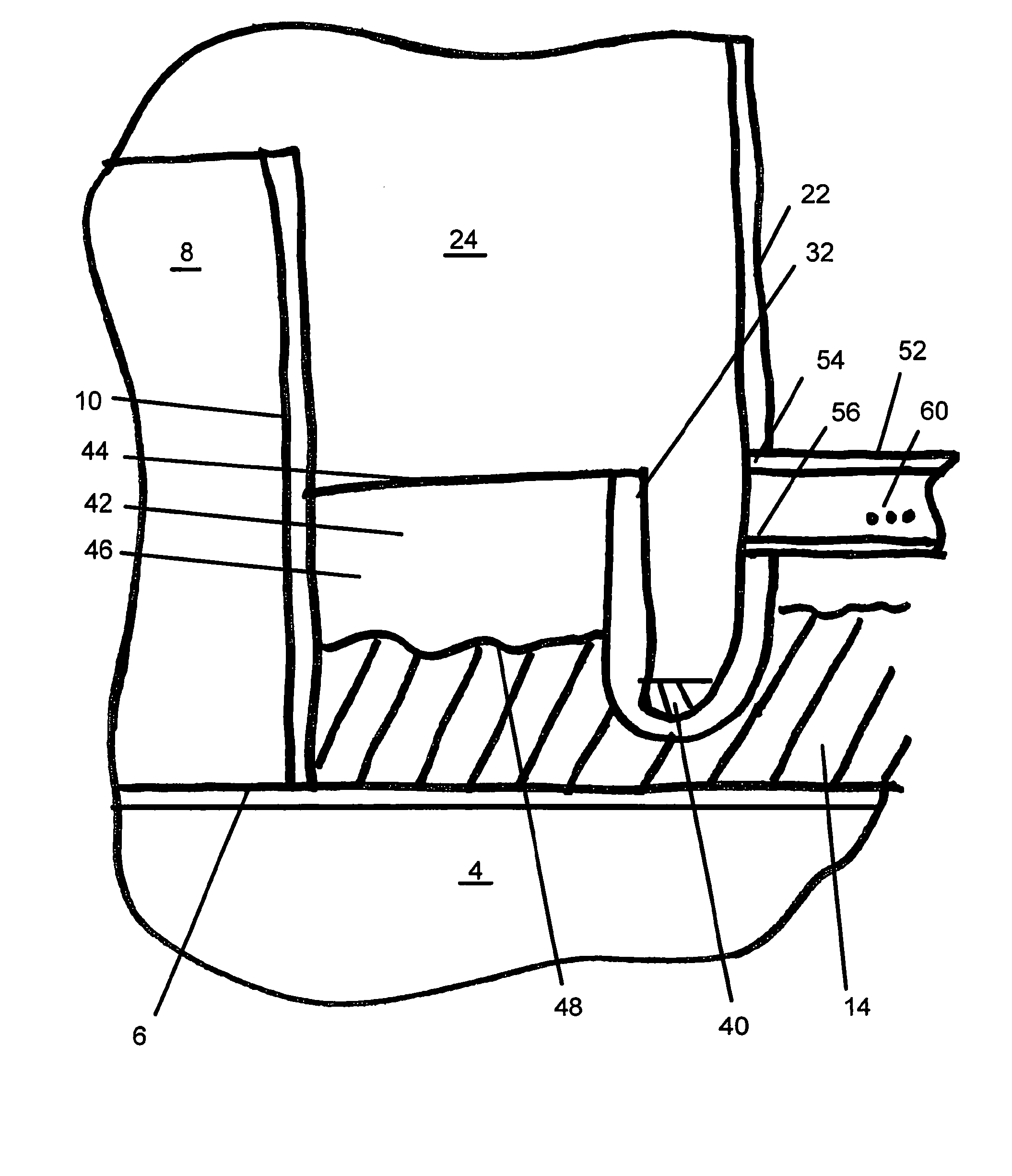
[0033]The Invention is an apparatus and method for preventing failure of an underground storage tank drainage system due to blinding of the drainage system by sediment. The Invention is also an apparatus and method for providing secondary containment for liquid released within a tank sump.

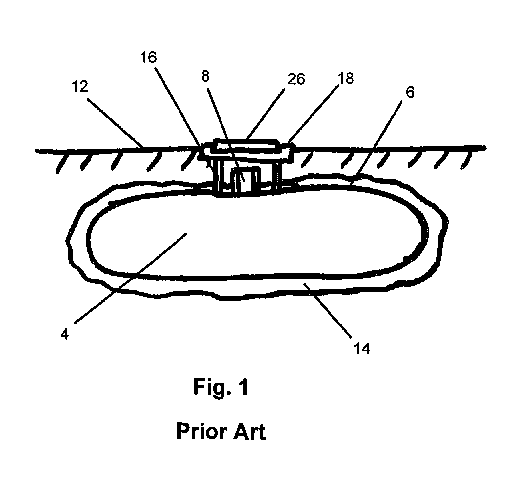
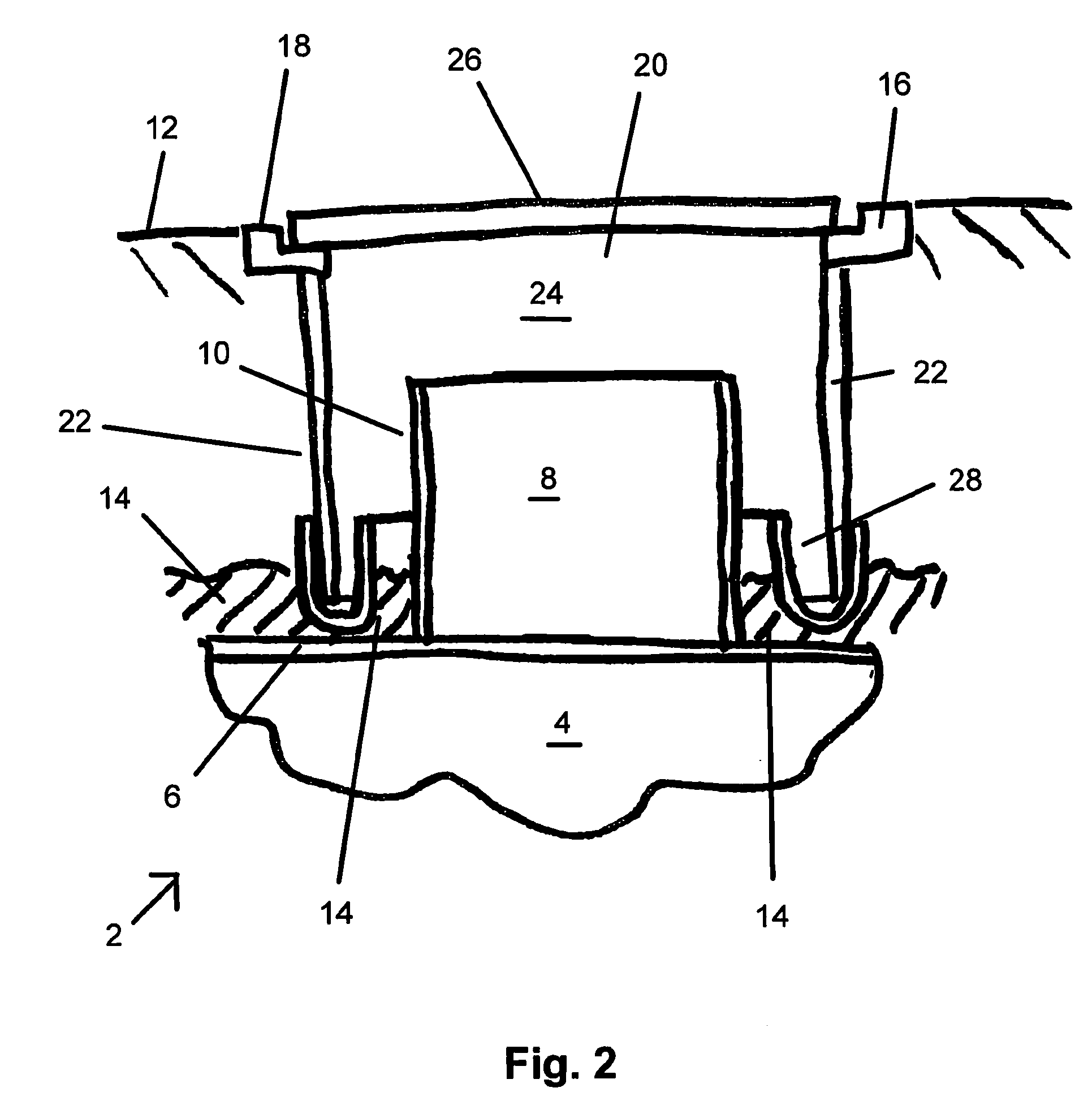
[0034]FIG. 1 illustrates a prior art underground storage tank system 2. An underground storage tank 4 is buried beneath the surface 12 of the ground. The underground storage tank 4 is surrounded in whole or in part by a drainage medium 14, as defined above. The drainage medium 14 serves to drain water away from the tank 4. A tank sump 8 is defined by sump perimeter wall 10, which is attached to a top side 6 of tank 4. Sump perimeter wall 10 forms a water and liquid-tight seal with top 6 of tank 4. Tank sump 8 contains tank 4 systems for access to the interior of the tank 4, such as a pump, vents, fill tubes, or other tank 4 systems or penetrations. Access to tank sump 8 is through a manway 24 from ...


PUM

PropertyMeasurementUnit
perimeteraaaaaaaaaa
volumeaaaaaaaaaa
interior volumeaaaaaaaaaa

Abstract

The Invention is an underground storage tank apparatus and method. A buried underground storage tank has a tank sump and a manway defined by a manhole skirt side wall communicating from the surface of the ground to the tank sump. A sediment trap is disposed annularly within the manway and intercepts water and sediment flowing down the manhole skirt wall. An inside wall of the sediment trap is in an annular spaced-apart relation with a tank sump perimeter watt, which together define an annular space interior volume that receives water that overtops the sediment trap inside wall and which receives liquid that overtops the tank sump perimeter wall.

Description

RELATED APPLICATIONS[0001]This application is entitled to priority from Provisional Application No. 61 / 111,885 filed Nov. 6, 2008 by David E. Stein. Provisional Application No. 61 / 111,185 file Nov. 4, 2008 is hereby incorporated by reference as if set forth in full herein.BACKGROUND OF THE INVENTION[0002]1. Field of the Invention[0003]The invention is an apparatus for the capture of sediment in water entering a manhole for an underground storage tank. The invention also is an apparatus providing secondary containment for spills of liquid from within a sump of an underground storage tank.[0004]2. Description of the Related Art[0005]The problem addressed by the Invention is the flooding of electrical pumps and other subterranean systems serving underground storage tanks due to the blinding of underground water drainage systems by sediment and debris.[0006]Underground storage tanks (“USTs”) are tanks designed to contain liquids such as petroleum products and are buried below the surfac...

Claims


Application Information

Patent Timeline
Patent Type & Authority Patents(United States)
IPC IPC(8): B65B1/04B05B3/04
CPCB65D88/76B65D90/105Y02A20/00
Inventor STEIN, DAVID E.
Owner J D STEIN
Why Eureka
Try Eureka