Card identification device, card identification method, program, and information recording medium

a card identification and card reader technology, applied in the field of card identification devices and card identification methods, can solve the problems of inability to be assembled into portable game consoles, high cost of barcode readers and magnetic card readers, etc., and achieve the effect of convenient positioning

Active Publication Date: 2012-04-17
KONAMI DIGITAL ENTERTAINMENT CO LTD
View PDF9 Cites 10 Cited by
  • Summary
  • Abstract
  • Description
  • Claims
  • Application Information

AI Technical Summary

Benefits of technology

[0060]According to the present invention, it is possible to provide a card identification device and a card identification method that allow easy locating of a card placed on a touch panel when identifying the card type of the card by sliding a pointer such as a touch pen or the like along a slit formed in the card, a computer-readable information recording medium that stores a program for realizing these on a computer, and the program.

Problems solved by technology

However, barcode readers and magnetic card readers are generally expensive and, in many cases, cannot be assembled into portable game consoles.

Method used


Image

  • Card identification device, card identification method, program, and information recording medium
  • Card identification device, card identification method, program, and information recording medium
  • Card identification device, card identification method, program, and information recording medium

Examples


embodiment 1

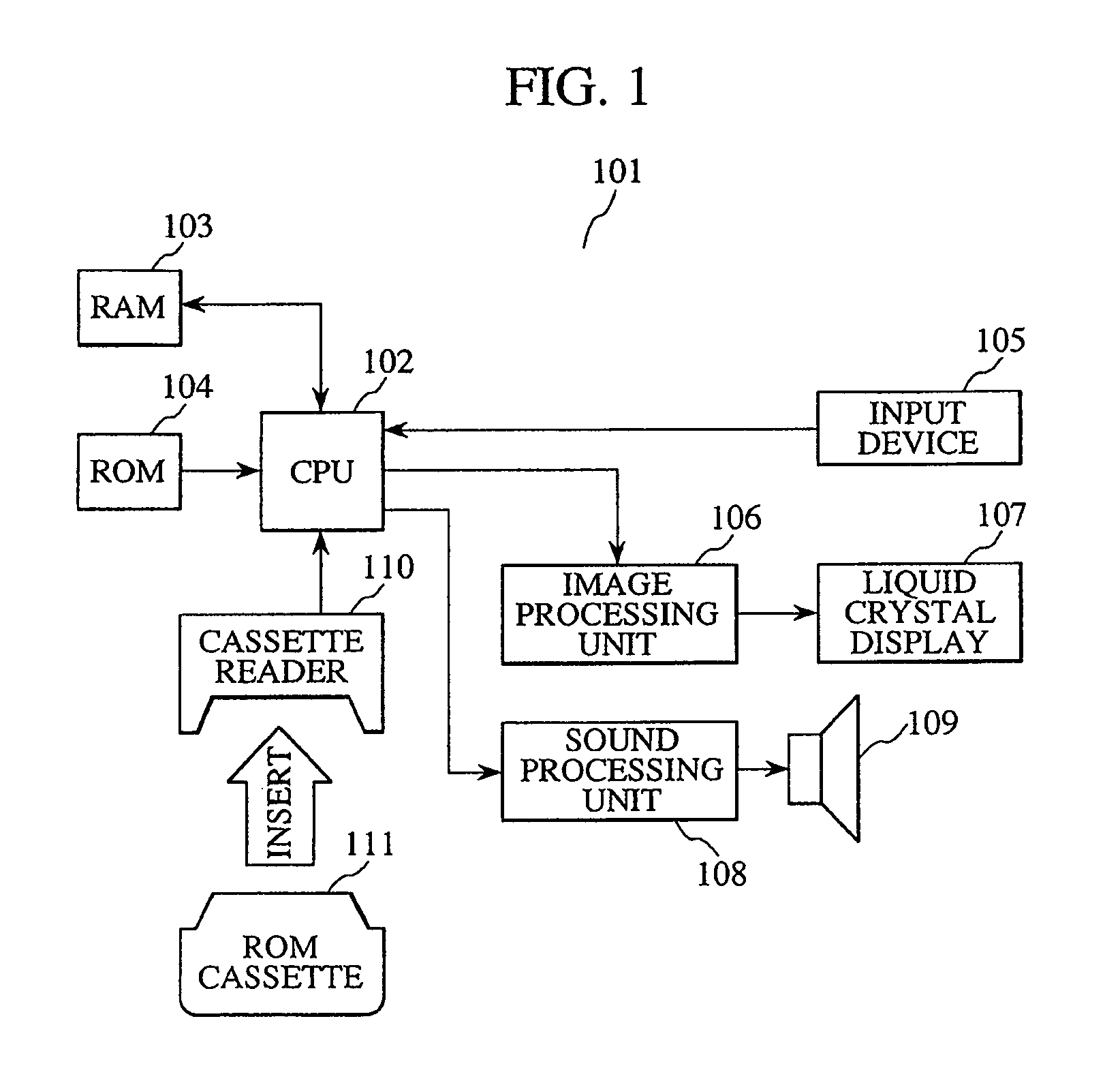
[0107]FIG. 1 is an exemplary diagram showing a schematic configuration of a typical information processing device that serves the functions of a card identification device according to the present invention by executing a program. The following explanation will be given with reference to FIG. 1.

[0108]The present information processing device 101 includes a Central Processing Unit (CPU) 102, a Random Access Memory (RAM) 103, a Read Only Memory (ROM) 104, an input device 105, an image processing unit 106, a liquid crystal display 107, a sound processing unit 108, a speaker 109, and a cassette reader 110.

[0109]The CPU 102 controls each unit of the present information processing device 101. The storage area of the RAM 103, the storage area of the ROM 104, and the storage area of a ROM cassette 111 inserted into the cassette reader 110 are all mapped to one memory space that is managed by the CPU 102, so the CPU 102 can acquire the information stored in each area by reading from the addr...

embodiment 2

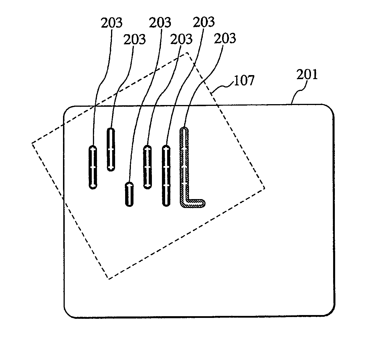
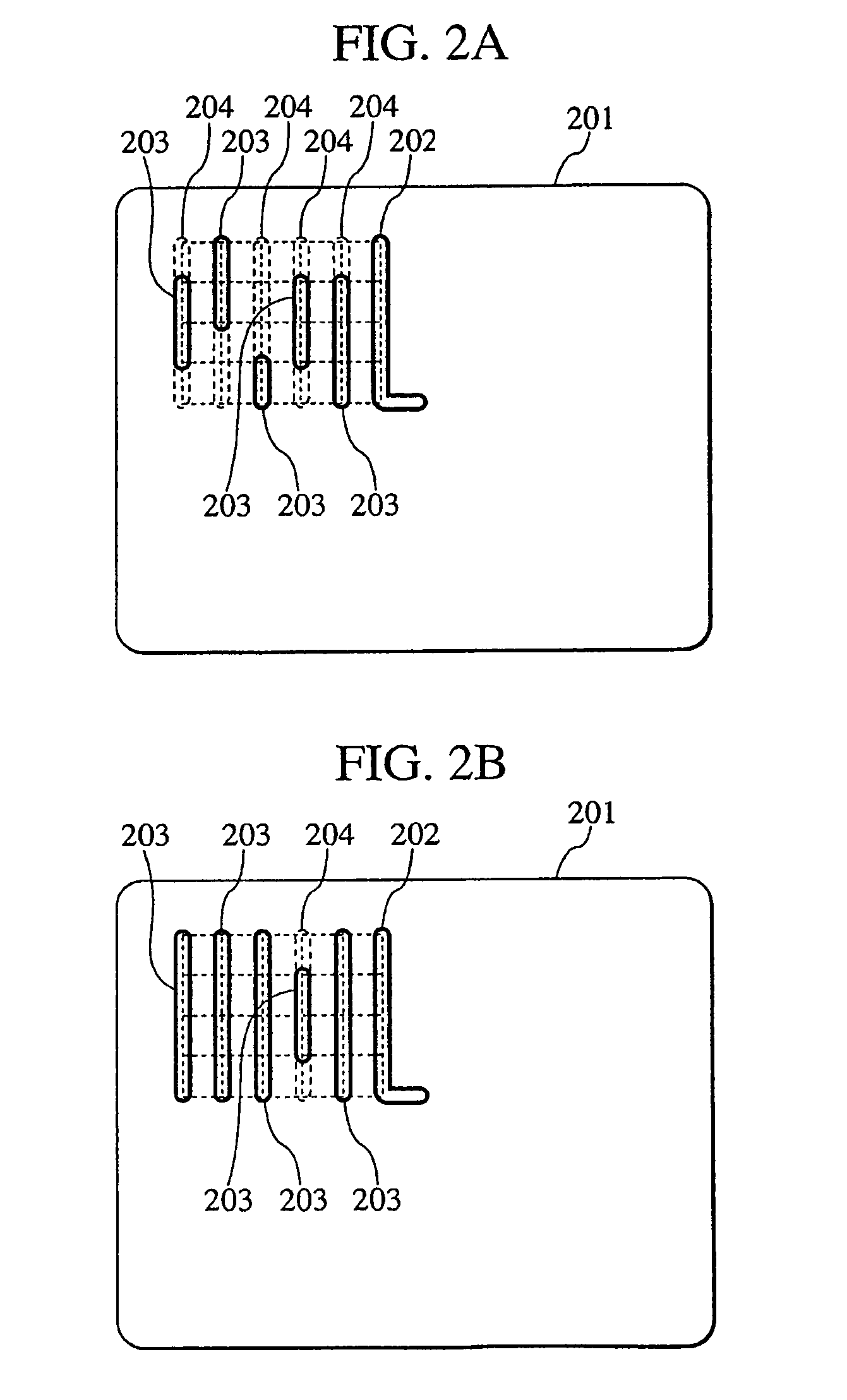
[0287]In the embodiment described above, the position of the reference slit 202 is identified by feeling the reference slit 202, the positions of the respective longest slit regions 204 are identified based on the identified position of the reference slit 202, and a plurality of center lines 602 and tolerance regions 603 are displayed as images 601 that represent the identified longest slit regions 204.

[0288]However, in some case, the order of inputting via the value slits 203 to feel them is fixed. For example, a method of feeling the value slits 203 from those closer to the reference slit 202 uses a fixed order. Such a method is advantageous in that it can more securely prevent any slit from being forgotten to input from.

[0289]In the case where the order of inputting via the value slits 203 is fixed, it is desired that the order is shown to the user. Hence, in the present embodiment, a method for showing the order to the user will be provided.

[0290]FIG. 11 are explanatory diagrams...


PUM


Abstract

Aimed is easy locating of a card placed on a touch panel, when identifying card type by sliding a touch pen, etc. along card slits. When a reference slit determining unit (404) of a card identification device (401) determines that a locus input from a touch panel unit (402) matches a reference slit, a slit region display control unit (405) displays longest slit regions images in which value slits are to be included on an image display unit (403). When a value slit determining unit (406) determines that a locus input thereafter matches any value slit, an input-finished slit display control unit (409) displays the image of the identified value slit on the image display unit (403), overlaying it on the longest slit region. When all value slits are identified, a card identifying unit (407) identifies the card type based on types of the identified value slits, and outputs it.

Description

TECHNICAL FIELD[0001]The present invention relates to a card identification device and a card identification method that allow easy locating of a card placed on a touch panel when identifying the type of the card by sliding a pointer such as a touch pen or the like along a slit formed in the card, a computer-readable information recording medium that stores a program for realizing these on a computer, and the program.BACKGROUND ART[0002]Techniques for computer card games that mimic games using real cards such as playing cards, Japanese playing cards, etc. have conventionally been proposed. Such a computer card game technique is disclosed in the following literature.[0003]Patent Literature 1: Unexamined Japanese Patent Application KOKAI Publication No. 2000-157744[0004][Patent Literature 1] discloses a technique that uses not a real card form of a given kind of cards but their form as information expressed by a computer, and makes the computer judge a victory or a defeat of a game, t...

Claims


Application Information

Patent Timeline
Patent Type & Authority Patents(United States)
IPC IPC(8): G06K7/00
CPCA63F1/18G06F3/041G06K19/063A63F2001/025A63F2009/241A63F2009/2422G06K2019/06271G06F3/04162G06F3/14
Inventor NITTA, HARUKI
Owner KONAMI DIGITAL ENTERTAINMENT CO LTD
Why Eureka
Try Eureka