Method and apparatus for real time spatial compound imaging

a compound imaging and real-time technology, applied in the field of ultrasonic imaging systems, can solve the problems of motion blur degrading the compounded image, and achieve the effect of automatically detecting and reducing motion blur

Active Publication Date: 2012-04-17
SHENZHEN MINDRAY BIO MEDICAL ELECTRONICS CO LTD
View PDF17 Cites 41 Cited by
  • Summary
  • Abstract
  • Description
  • Claims
  • Application Information

AI Technical Summary

Benefits of technology

[0007]Furthermore, since a user need constantly move a probe to locate a scan target during the scanning phase. Motion blur will degrade the compounded image due to the low time resolution from a steering scan cycle. To tackle this problem, the present invention proposes an ultrasonic imaging system and method which can automatically detect and reduce the motion blur inside the spatial compounding loop.

Problems solved by technology

Motion blur will degrade the compounded image due to the low time resolution from a steering scan cycle.

Method used


Image

  • Method and apparatus for real time spatial compound imaging
  • Method and apparatus for real time spatial compound imaging
  • Method and apparatus for real time spatial compound imaging

Examples


example 1

[0022]FIG. 4 is a schematic configuration illustrating an image compounding device 100 for an ultrasonic imaging system in accordance with the present invention. The image compounding device 100 comprises a buffer 101, a memory 102, a differential image computing unit 103, a pre-processing unit 104, an accumulator 105 and a post-processing unit 106.

[0023]The buffer 101 receives a newly sampled component image C(i, j) having a certain steering angle from an envelope detecting unit and has it buffered, where C(i, j) denotes a component image at the jth steering angle acquired in the ith steering scan cycle. A steering scan cycle is defined as a period used to scan and image the target at a predetermined number of steering angles. The memory 102 includes a plurality of storage areas which are adapted for storing the received component images and the compounded images respectively. Each of the plurality of storage area is set to zero during initialization.

[0024]The differential image co...

example 2

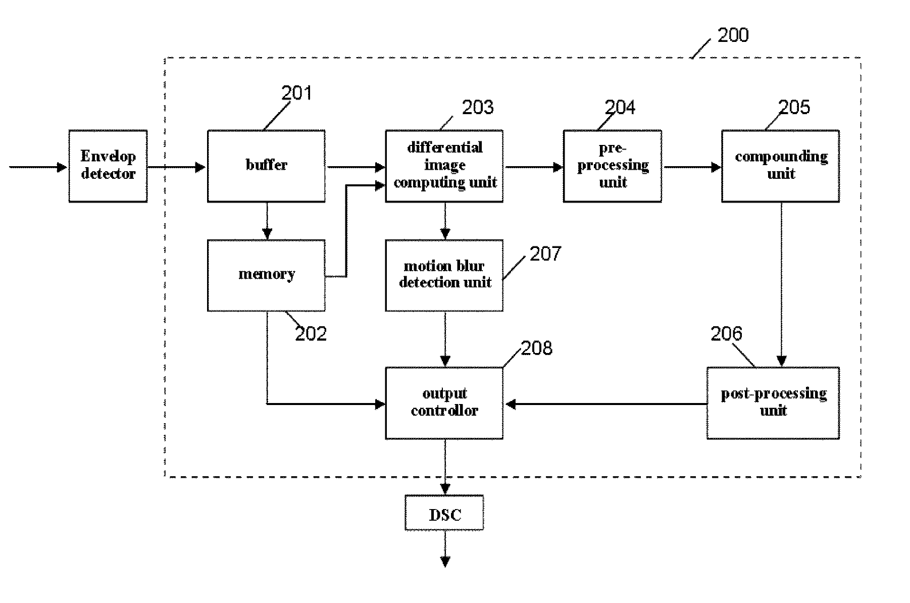
[0036]FIG. 7 is an image compounding device 200 in accordance with the second embodiment of the present invention, which differs from the first embodiment in that a motion blur detection and control mechanism is introduced in this embodiment. Specifically, besides those elements of the first embodiment, the image compounding device 200 further comprises: motion blur detecting unit 207 for estimating the degree of the motion blur in the image based on the amplitude of the differential image at each steering angle; output control unit 208 for selectively controlling the image output to DSC for display based on the detection result of the motion blur detecting unit 207, wherein a component image stored in the memory 102 is outputted to DSC in case there exists a heavy motion blur and otherwise a compounded image is outputted to DSC.

[0037]The amplitude of the differential image can, for example, be presented by the summation of the absolute values of the differential image (SAD). If the...


PUM


Abstract

The present invention provides a method and device for spatial compound imaging. The method comprises steps of receiving a component image C(i, j), where i denotes a steering scan cycle, and j a steering angle of the component image; computing a differential image by subtracting a component image C(i−1,j) from the component image C(i, j) with the same steering angle from a previous steering scan cycle; pre-processing said differential image; compounding the pre-processed differential image and a previous compounded image to form a new compounded image.

Description

FIELD OF THE INVENTION[0001]The present invention relates to an ultrasonic imaging system and, in particular, to an ultrasonic imaging system using the spatial compounding technique.BACKGROUND OF THE INVENTION[0002]In ultrasonic diagnostic imaging system, spatial compounding technique is often used to reduce speckle noise, acoustic shadow and reverberation of the ultrasonic image and improve contrast and signal-to-noise ratio. As a result, the definition and readability of the ultrasonic images are improved. The spatial compound imaging technique typically images an object from multiple angles by steering scan beams. FIG. 1 shows a view of spatial compounding by using a component image C(i, j) of a linear array probe at three steering angles, wherein C(i, j) denotes the jth component image during the ith steering scan cycle (time taken to image an object three times at three steering angles is defined as a steering scanning cycle). It can be seen that the component images at the thr...

Claims


Application Information

Patent Timeline
Patent Type & Authority Patents(United States)
IPC IPC(8): A61B8/00
CPCG01S15/8995G01S7/52034G01S7/5205
Inventor ZHANG, YUWANG, YONG
Owner SHENZHEN MINDRAY BIO MEDICAL ELECTRONICS CO LTD
Why Eureka
Try Eureka