
Process for the internal welding of plastic tubes

a technology of plastic tubes and internal welding, which is applied in the field of tubular packaging, can solve the problems of reducing the visibility of the weld zone, pronounced and matt weld zone, etc., and achieves the effects of facilitating or improving the welding conditions, increasing the lateral contact area of the laminate, and reducing the influence of quality and strength of welds

Active Publication Date: 2012-04-17
AISAPACK HLDG SA
View PDF12 Cites 5 Cited by
  • Summary
  • Abstract
  • Description
  • Claims
  • Application Information

AI Technical Summary

Benefits of technology

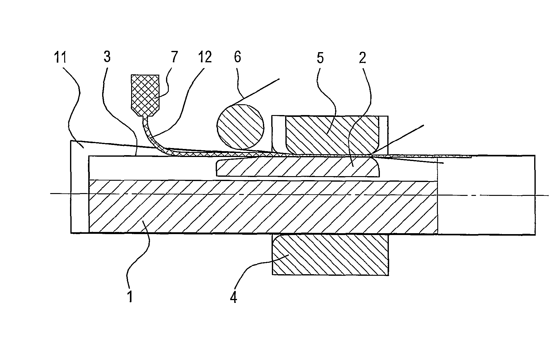
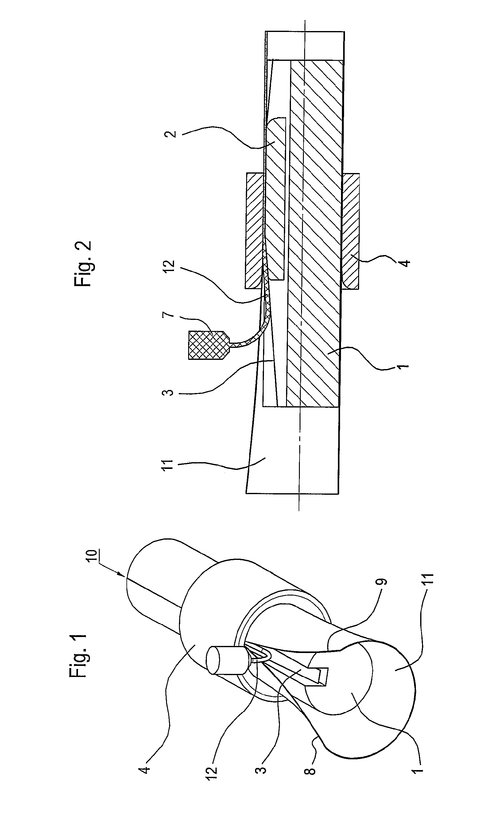
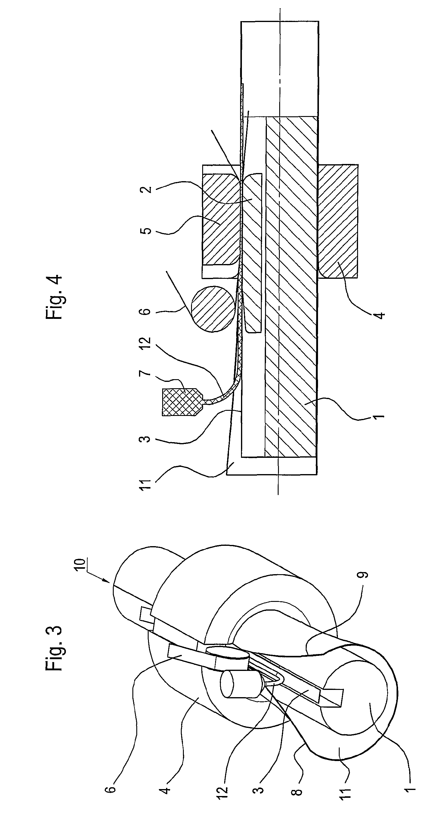
"The present invention proposes a solution to the problem of weakness in butt welds and the need for an attractive weld. The solution involves reinforcing the weld with a bead of plastic. The process for manufacturing plastic packaging in tubular form involves wrapping a laminate, butting the edges of the laminate together, and fastening them. The bead of plastic is extruded and deposited on the internal face of the packaging to cover at least the zone defined between the edges. The invention has several advantages, including the use of a bead of plastic that comes from the inside of the tube, eliminating the need for a complex high-frequency welding system. The external appearance of the tube is perfect, and there is no contact between the product and the barrier layer of the laminate."

Problems solved by technology

However, there is a need to bring the edges into direct contact with each other (butt welding), for technical and aesthetic reasons.
Moreover, the absence of a welding element on the external face reduces the visibility of the weld zone.
The heating systems of the prior art are placed on the outside of the tube and their activation necessarily results in a pronounced and matt weld zone.

Method used


Image

  • Process for the internal welding of plastic tubes
  • Process for the internal welding of plastic tubes
  • Process for the internal welding of plastic tubes

Examples


Embodiment Construction

[0028]The invention will be described in greater detail below by means of examples illustrated by the following figures:

[0029]FIG. 1 is a perspective view of a first device according to the invention;

[0030]FIG. 2 is a lateral section of the device of FIG. 1;

[0031]FIG. 3 is a perspective view of a second device according to the invention;

[0032]FIG. 4 is a lateral section of the device of FIG. 3;

[0033]FIG. 5 is a perspective view of a third device according to the invention;

[0034]FIG. 6 is a lateral section of the device of FIG. 5;

[0035]FIG. 7 is a perspective view of a fourth device according to the invention;

[0036]FIG. 8 is a lateral section of the device of FIG. 7;

[0037]FIG. 9 is a perspective view of a fifth device according to the invention;

[0038]FIG. 10 is a lateral section of the device of FIG. 9;

[0039]FIG. 11 shows a first variant of a weld according to the invention;

[0040]FIG. 12 shows a second variant of a weld according to the invention;

[0041]FIG. 13 shows a third variant o...


PUM

PropertyMeasurementUnit
temperatureaaaaaaaaaa
energyaaaaaaaaaa
homogeneityaaaaaaaaaa

Abstract

The invention relates to a process for manufacturing plastic packaging in tubular form, which process comprises a wrapping step during which a laminate (11) is wrapped, an abutting step during which the edges (8, 9) of the laminate (11) are butted together and a fastening step during which said edges (8, 9) of the laminate (11) are welded together, characterized in that a bead (12) of plastic in the molten state is extruded and deposited on the internal face of the packaging so as to cover at least the weld zone (10) defined between the edges. The energy needed to produce the weld (10) comes from the plastic bead (12).The invention also relates to packaging obtained from the aforementioned process and to a device for implementing said process.

Description

[0001]This application is the U.S. national phase of International Application No. PCT / IB2007 / 053842, filed 21 Sep. 2007, which designated the U.S. and claims priority to EP Application No. 06121466.4, filed 28 Sep. 2006, the entire contents of each of which are hereby incorporated by reference.FIELD OF THE INVENTION[0002]The invention relates to the field of tubular packaging, especially consisting of a wrapped plastic laminate. More precisely, the invention relates to wrapped laminates, the edges of which do not overlap.PRIOR ART[0003]The welding of the edges of a laminate so as to obtain a tubular body usually takes place with an overlap. See for example German Patent Application DE 2008085.[0004]When it is desired to place the edges face to face, a gap is left between them which is filled with a material, such as a strip of plastic, the strip acting as a welding element. See for this purpose European Patent Application EP 0 000 643.[0005]However, there is a need to bring the edg...

Claims


Application Information

Patent Timeline
Patent Type & Authority Patents(United States)
IPC IPC(8): B29C53/50B31B50/62
CPCB29C53/382B29C66/836B29C53/50B29C65/40B29C65/5042B29C65/5071B29C66/00441B29C66/1142B29C66/4322B29C66/63B29C53/387B29L2009/00B29L2023/00B29C65/4815Y10T428/1345Y10T156/1013Y10T428/1359B29C65/18B29C65/72B29C65/7894B29C66/49B29C66/71B29C66/723B29C66/72321B29C66/7234B29C66/83421B29K2023/06B29K2023/12B29C53/38B65D35/00
Inventor VOIGTMANN, JEAN-PIERRE
Owner AISAPACK HLDG SA
Learn More