Contact-less power supply, contact-less charger systems and method for charging rechargeable battery cell

a rechargeable battery and charger technology, applied in the direction of safety/protection circuits, inductances, transportation and packaging, etc., can solve the problems of poor contact state, battery is apt to lose charging energy, and the effect of affecting charging efficiency

Active Publication Date: 2012-04-17
LS CABLE & SYST LTD
View PDF32 Cites 54 Cited by
  • Summary
  • Abstract
  • Description
  • Claims
  • Application Information

AI Technical Summary

Benefits of technology

[0011]It is an object of the present invention to provide a contact-less power supply which effectively transmits induced electromotive force to a secondary battery device regardless of positional relationship between a primary coil and a secondary coil.
[0013]And, it is another object of the present invention to provide a contact-less power supply which realizes high charging efficiency and minimizes waste of energy.Technical Solution
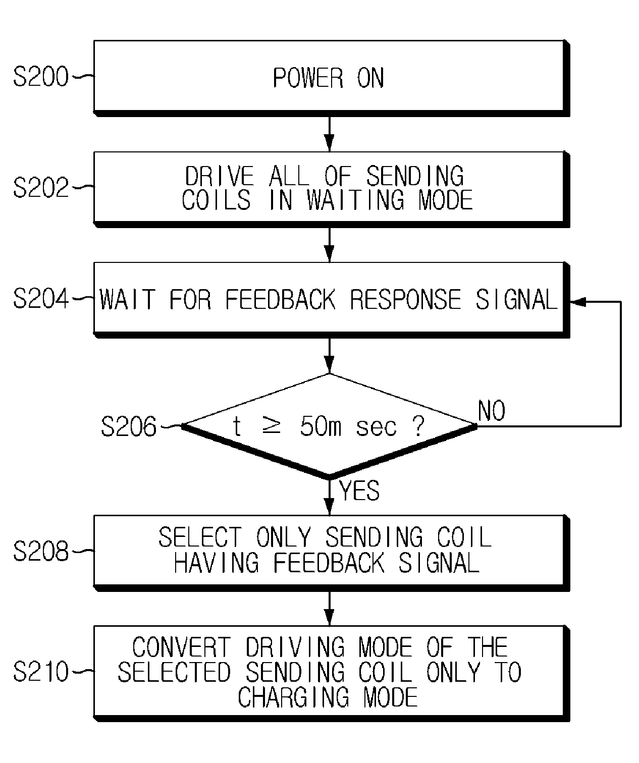
[0019]A charging method for charging a battery in accordance with a third aspect of the present invention, in a contact-less charger system composed of a power supply including a primary coil array having a plurality of primary coils and a wireless receiving module, and a battery device having a secondary coil magnetically coupled to the primary coil, a wireless sending module and a rechargeable battery, includes (A) selecting any one of the primary coils and preliminarily driving the selected primary coil during a relatively short time; (B) waiting for a feedback response from the battery device during a predetermined time; (C) in case the feedback response exists, temporarily storing identification information of the corresponding primary coil in a memory; (D) selecting another primary coil from the primary coil array and repetitively performing the steps (A) to (C); (E) sequentially performing the step (D) on all of the primary coils of the primary coil array; and (F) reading the identification information of the primary coil from the internal memory and selectively supplying a charging power to only the corresponding primary coil.
[0021]And, a charging method for charging a battery in accordance with a fifth aspect of the present invention, in a contact-less charger system composed of a power supply including a primary coil array having a plurality of primary coils and a wireless receiving module, and a battery device having a second coil magnetically coupled to the first coil, a wireless sending module and a battery, includes (A) preliminary driving simultaneously all of the primary coils of the primary coil array during a relatively short time; (B) waiting for a feedback response from the battery device during a pre-determined time; (C) selecting at least one primary coil having the feedback response; and (D) charging the battery device by applying a charging power to the selected primary coil.

Problems solved by technology

However, if the contact terminals protrude outward, this leads to bad appearance and the contact terminals are contaminated by external impurities, resulting in poor contact state.
And, if the battery is disconnected or exposed to moisture due to a user's carelessness, the battery is apt to lose the charging energy.
However, the above-mentioned conventional contact-less charger systems have a disadvantage that the charging efficiency depends on the positional relationship between the primary coil and the secondary coil.
That is, in case positional offset exists between the primary coil and the secondary coil, induced electromotive force is insufficiently induced to the secondary coil, and thus the contact-less charger system has lower charging efficiency than a contact-type charger system.
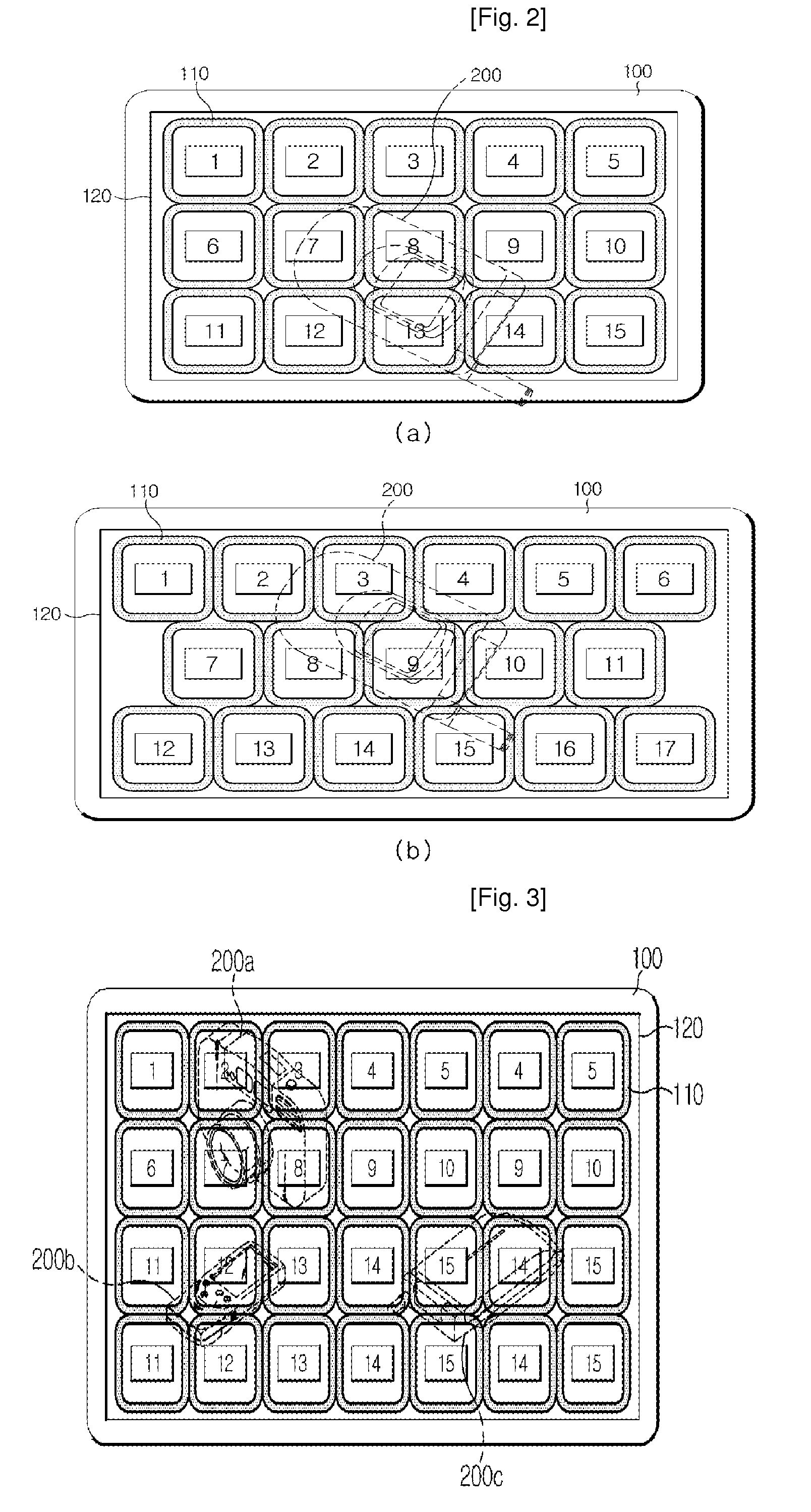
The above 254' patent arranges a plurality of coils alternately or parallel on the same plane of the charging body to compensate for positional offset between a primary coil and a secondary coil, which results in excessive waste of energy, compared with a contact-less charger system using a single coil.

Method used


Image

  • Contact-less power supply, contact-less charger systems and method for charging rechargeable battery cell
  • Contact-less power supply, contact-less charger systems and method for charging rechargeable battery cell
  • Contact-less power supply, contact-less charger systems and method for charging rechargeable battery cell

Examples


Embodiment Construction

[0032]Hereinafter, preferred embodiments of the present invention will be described in detail with reference to the accompanying drawings. Prior to the description, it should be understood that the terms used in the specification and the appended claims should not be construed as limited to general and dictionary meanings, but interpreted based on the meanings and concepts corresponding to technical aspects of the present invention on the basis of the principle that the inventor is allowed to define terms appropriately for the best explanation. Therefore, the description proposed herein is just a preferable example for the purpose of illustrations only, not intended to limit the scope of the invention, so it should be understood that other equivalents and modifications could be made thereto without departing from the spirit and scope of the invention.

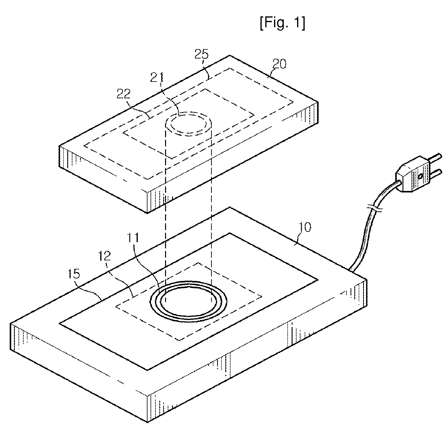
[0033]FIG. 1 is a schematic perspective view of a conventional contact-less charger system for describing a contact-less charging prin...


PUM

PropertyMeasurementUnit
current voltageaaaaaaaaaa
frequencyaaaaaaaaaa
timeaaaaaaaaaa

Abstract

The present invention relates to a contact-less power supply magnetically coupled to a battery device having a receiving coil therein, for contact-less charging the battery device, the contact-less power supply having a sending coil array including a plurality of sending coils for inducing a charging power to the receiving coil; and a driving means for detecting a sending coil magnetically coupled to the receiving coil and selectively driving only the detected sending coil.

Description

CROSS-REFERENCE TO RELATED APPLICATIONS[0001]This application is a national stage application under 35 U.S.C. 371 based on and claiming the benefit of International Application Serial No. PCT / KR2007 / 000392 filed on Jan. 23, 2007 and the benefit of priority from Korean Application No. 10-2006-0009304filed on Jan. 31, 2006, the entire contents of each of which are incorporated herein by reference.TECHNICAL FIELD[0002]The present invention relates to a power supply for a portable electronic equipment, and in particular, to a contact-less charger system using inductive coupling.BACKGROUND ART[0003]A rechargeable secondary electric cell (i.e. a battery) is mounted in a portable electronic equipment such as a mobile communication terminal, a PDA and so on. To charge the secondary electric cell (i.e. battery), it requires a separate power supply for supplying electric energy to the battery of the portable electronic equipment using a commercial power source for domestic use. Typically, eac...

Claims


Application Information

Patent Timeline
Patent Type & Authority Patents(United States)
IPC IPC(8): H02J7/00H01F38/14
CPCH02J7/025H02J50/90H02J7/00304H02J7/00308H02J50/10H02J50/40H04B5/0037H04B5/0075
Inventor CHOI, SUNG-UKKWON, KWANG-HEEKIM, JUNG-BUMMOON, SUNG-WOOKPARK, DONG-YOUNGHAN, SUB
Owner LS CABLE & SYST LTD
Why Eureka
Try Eureka